Oil Pump Installation
- Clean the intermediate support plate and oil pump with suitable solvent and blow them dry with regulated 344 kPa (50 psi) shop air.
- Inspect the intermediate support plate and oil pump for apparent damage or wear. If the intermediate support plate is damaged, the transmission will require replacement. If the oil pump is damaged, replace the oil pump.
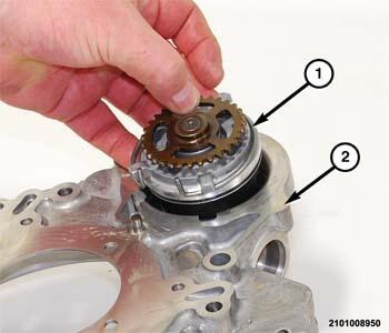
- Insert the oil pump (1) into the intermediate support plate (2). Align the tabs on the pump with the notches on the intermediate support plate.
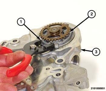
- Using a suitable pliers (1), compress the oil pump snap ring.
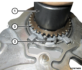
- While holding compression on the snap-ring (2), use (special tool #2016200211, Remover-Installer, 948 TE Transmission Pump) (1) with a C-clamp to compress the spring on the bottom of the oil pump just enough to seat the snap-ring (2).
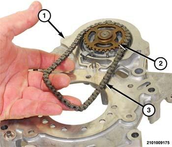
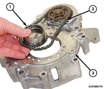
- Install the oil pump drive chain (3) onto the oil pump driven sprocket (2).
- Install the oil pump drive sprocket (1) onto the drive chain (2).
- While holding the chain on the drive sprocket (1), turn the intermediate support plate and oil pump over on the work surface.
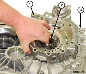
- Place the intermediate support plate and oil pump (1) in position on the bellhousing (3).
- Insert the oil pump drive sprocket into the oil pump sprocket needle bearing.
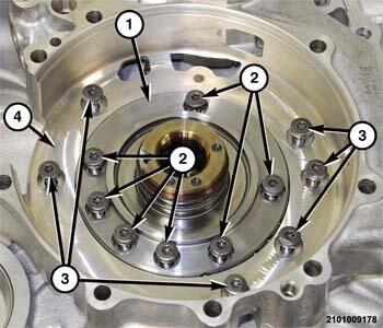
- Install the bolts (3) to hold the intermediate support plate and oil pump (1) to the bellhousing and tighten to the proper torque specifications. Refer to TECHNICAL SPECIFICATIONS .
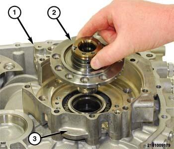
- Place the reaction shaft (2) into the intermediate support plate (3).
- Install the bolts (2) to hold the reaction shaft (1) to the intermediate support plate (4) and tighten to the proper torque specifications. Refer to TECHNICAL SPECIFICATIONS .
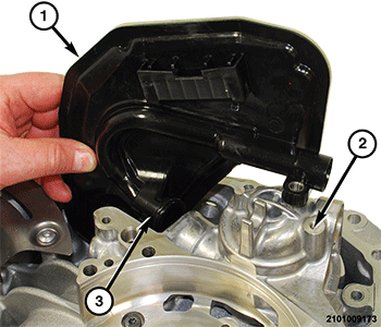
- Insert the oil filter neck (3) into the oil pump bore and align the bolt hole with the tapped hole in the intermediate support plate (2).
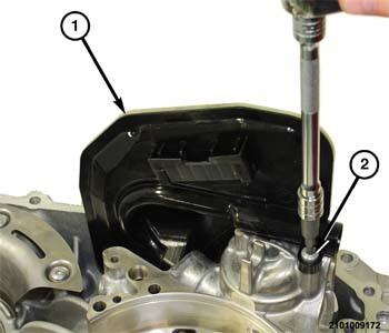
- Install the bolt (2) to hold the oil filter (1) to the intermediate support plate and tighten to the proper torque specifications. Refer to TECHNICAL SPECIFICATIONS .
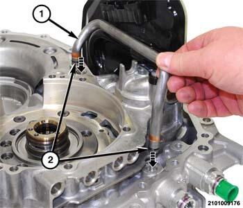
- Replace the O-ring seals (2) on the fluid tube (1).
- Install the fluid tube (1) into the bellhousing and intermediate support plate.
- Install the bellhousing on the transmission. Refer to BELLHOUSING, REMOVAL AND INSTALLATION .
- Install the transmission in the vehicle. Refer to REMOVAL AND INSTALLATION .
- Road test the vehicle to verify the repair.