Two Piece Driveshaft
- Raise and support the vehicle
Refer to HOISTING, STANDARD PROCEDURE .
NOTE:The suspension must be at normal ride height. Any altered suspension may cause vibration inducing operating angles.
- Support the vehicles suspension and lower vehicle until the suspension is at normal ride height.
- Place the vehicle in neutral "N".
- Inspect the center support bearing for damage or excess wear.
- Remove the universal joint snap rings if equipped, so the inclinometer base sits flat.
- Rotate the shaft until the transmission/transfer case output yoke bearing is facing downward.NOTE:
Always take measurements from front to rear and on the same side of the vehicle.
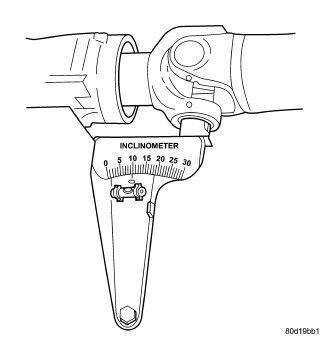
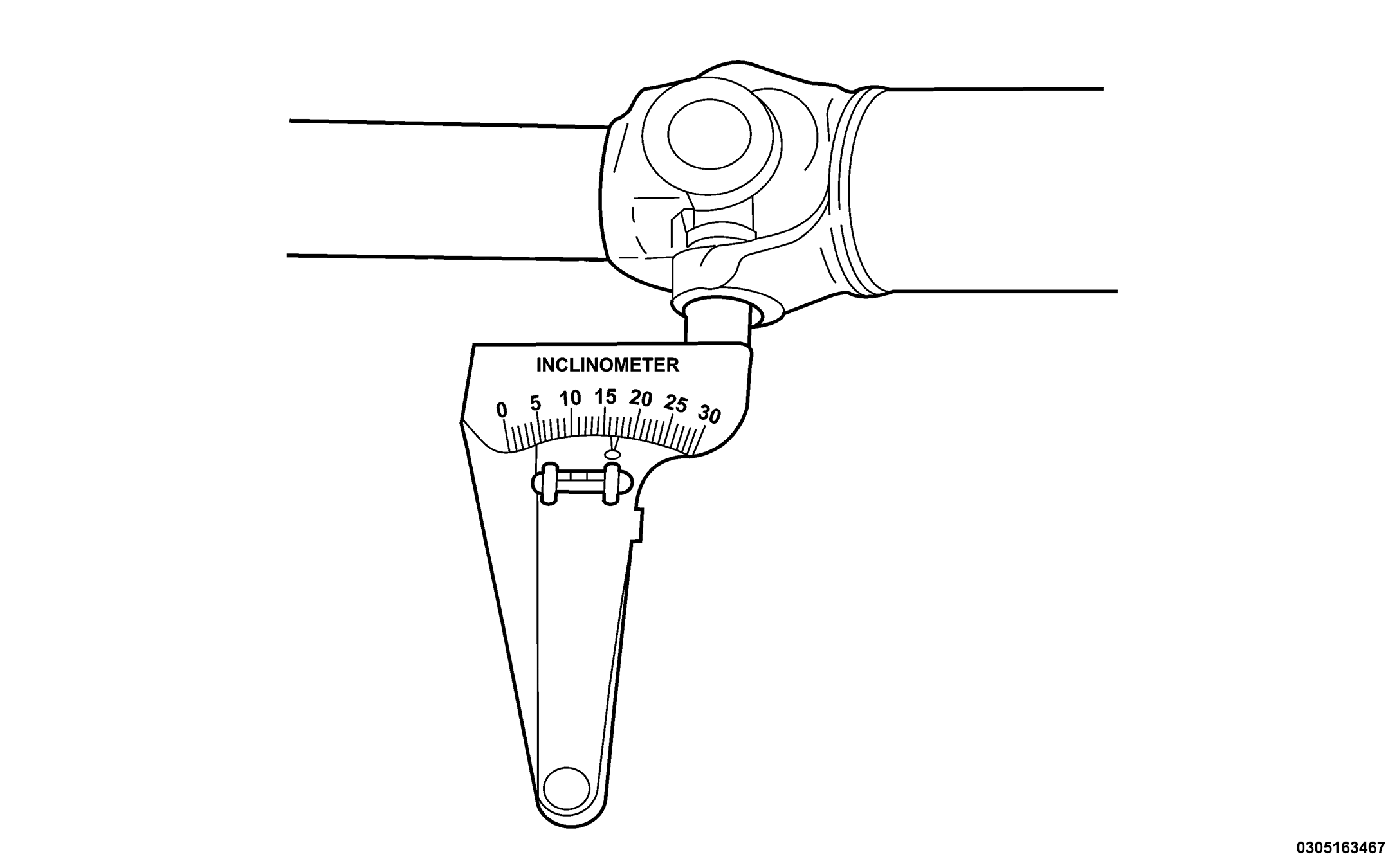
- Place the Inclinometer (special tool #7663, Inclinometer) on the yoke bearing cap or pinion flange ring perpendicular to the shaft. Place the inclinometer at zero degrees and turn the shaft to center the bubble in the sight glass.
- Place the Inclinometer (special tool #7663, Inclinometer) on the yoke bearing cap or pinion flange ring parallel to the shaft. Center the bubble in the sight glass and record the measurement (A).
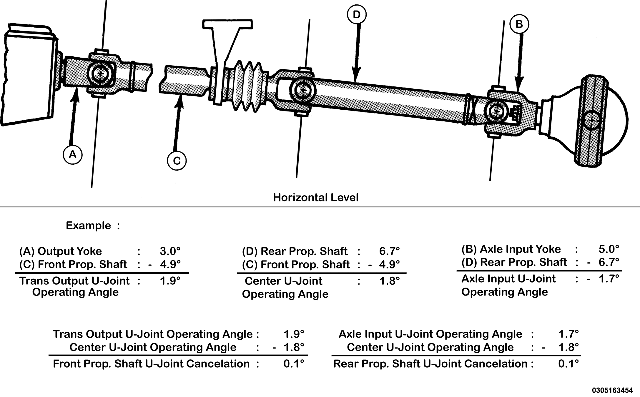
This measurement will give you the transmission yoke Output Angle (A).
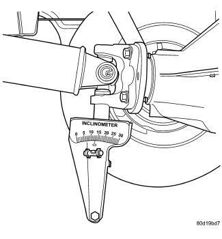
- Place the Inclinometer (special tool #7663, Inclinometer) on the center universal joint bearing cap parallel to the shaft. Center the bubble in the sight glass and record the measurement (D).
This measurement will give you the Rear Prop. Shaft Angle (D).
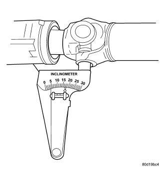
- Place the inclinometer on the companion flange yoke bearing parallel to the shaft. Center the bubble in the sight glass and record the measurement.
This measurement will give you the pinion Companion Flange Input Angle (B).
- Place the Inclinometer on the front driveshaft yoke bearing perpendicular to the shaft. Place the inclinometer at zero degrees and turn the shaft to center the bubble in the sight glass.
- Rotate the Inclinometer on the front driveshaft yoke bearing perpendicular to the shaft. Center the bubble in the sight glass and record the measurement. This measurement can also be taken at the rear end of the shaft. This measurement will give you the Front Prop. Shaft Angle (C).
- Subtract (A) minus (C) to obtain the Transmission/Transfer Case Output Universal Joint Operating Angle .
- Subtract (B) minus (C) to obtain the Center Universal Joint Operating Angle .
- Subtract (B) minus (D) to obtain the Axle Input Universal Joint Operating Angle .
- Subtract the Transmission/Transfer Case Output Universal Joint Operating Angle minus the Center Universal Joint Operating Angle to get the Front Propeller Shaft Universal Joint Cancelation .
- Subtract the Axle Input Universal Joint Operating Angle minus the Center Universal Joint Operating Angle to get the Rear Prop. Shaft Universal Joint Cancelation .
Refer to rules and example for additional information.
RULES
- Good cancellation of U-joint operating angles should be within 1 degree.
- Keep operating angles less than 10 degrees for double cardan U-joint.
- Operating angles should be less than 3 degrees.
- Maintain at least 1/2 of one degree continuous operating propeller shaft angle.
CHECKS IF MEASUREMENT OUTSIDE OF DESIRED OPERATING ANGLES
- Check condition of engine and transmission mounts.
- Check center support bearing for damage or excess wear.
- Check center support bearing adjustment.
- Check for proper vehicle ride height.
- Check condition of any hardware and bushings at axle the measurement is outside of desired operating angle.
- Inspect for collision damage that may account for the measurement outside of desired operating angle.