Disassembly And Assembly: Disassembly
The 948TE automatic transmission can be overhauled if the vehicle is beyond its warranty coverage. Verify that the vehicle is no longer covered by warranty, and that applicable parts for overhaul are available before beginning this procedure. A clean work area is necessary to assure a properly functioning transmission after the overhaul procedures are completed. Special tools have been developed and are required to disassemble this transmission. Acquire all of the special tools before starting this procedure.
Always wear safety glasses when cleaning, disassembling and assembling the transmission/transaxle. Contents of the transmission/transaxle can become projectiles (e.g., springs, snap-rings, as well as metal and other debris). Failure to wear safety glasses may result in severe personal injury.
Tag all snap rings, thrust washers, washers, shims, spacers and thrust bearings, etc. during disassembly for quick identification and assembly. Failure to follow these instructions will cause damage and transmission failure.
- Before disassembling the transmission, wash the transmission with a suitable solvent and a siphon pressure washer to remove oily grime and loose dirt. Place the transmission on a clean work surface with ample fluid drainage or absorbency.
- Check input shaft end play prior to disassembling the transmission. Refer to STANDARD PROCEDURES .
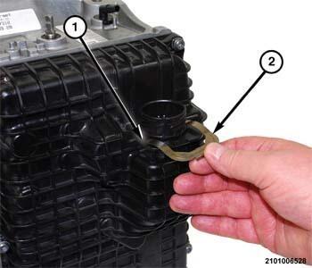
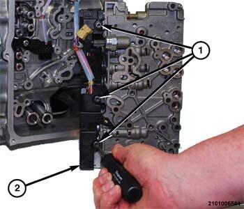
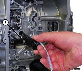
- Remove the clip (2) holding the transmission solenoid connector (1) in the valve body cover pan.
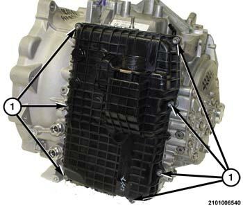
- Remove the valve body cover pan bolts (1) and the valve body cover pan.
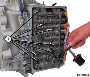
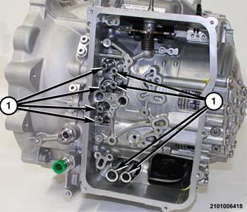
- Remove the larger bolts (1) holding the valve body to the transmission housing.
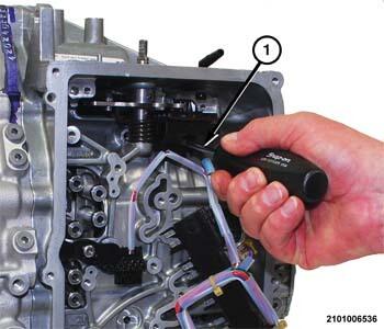
- Using a suitable prying tool, pry the valve body away from the fluid transfer tubes.
- Turn the valve body over to gain access to wire harness connectors.
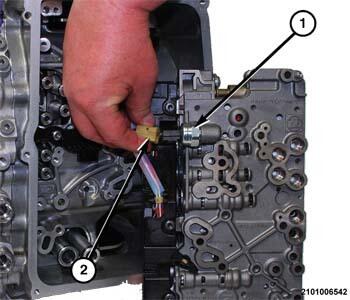
- Release the lock on the fluid pressure transducer wire harness connector (2) and separate the wire harness connector (2) from the transmission fluid pressure sensor (1).
- Remove the bolts (1) holding the transmission solenoid wire harness connector to the valve body and solenoids.
- Using a suitable prying tool, separate the transmission solenoid wire harness connector (2) from the solenoids.
- Separate the valve body from the transmission.NOTE:
If the valve body is to be reused without disassembling it, store the valve body in a clean area until it is installed.
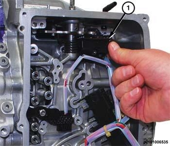
- Remove the Transmission Range Sensor (TRS) screw (1).
- Separate the TRS (1) from the transmission with the wire harness connected.
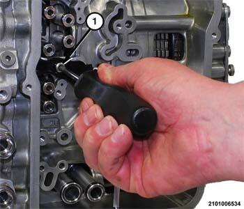
- Remove the speed sensor screw (1).
- Separate the speed sensor (1) from the transmission with the wire harness connected.
- Using suitable pliers, remove the fluid transfer tubes (1) from the transmission.
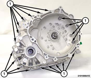
- From around the perimeter of the transmission, remove the bellhousing bolts (1) holding the bellhousing to the transmission housing.
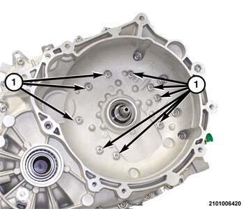
- Remove the bellhousing bolts (1) holding the bellhousing to the output gear support.
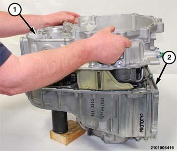
- Using wooden blocks to stabilize the transmission on the work surface, position the transmission on the bench with the bellhousing facing upward.
- Using a suitable pry-bar in the pry point locations, pry upward to dislodge the bellhousing from the transmission housing.
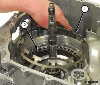
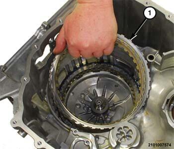
- Lift the bellhousing (1) upward and separate the assembly from the transmission housing (2).
- Remove the seal (1) from the port in the transmission housing.
- Separate the gasket (1) from the sealing surface of the transmission housing (2).
- Remove the differential assembly (1) from the transmission housing.
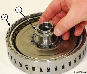
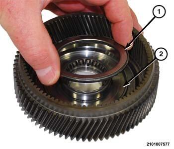
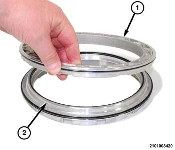
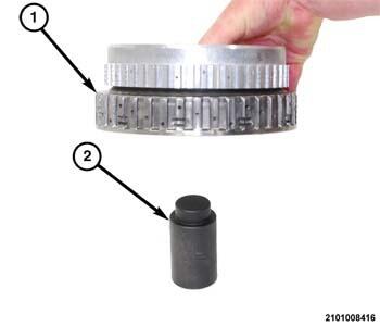
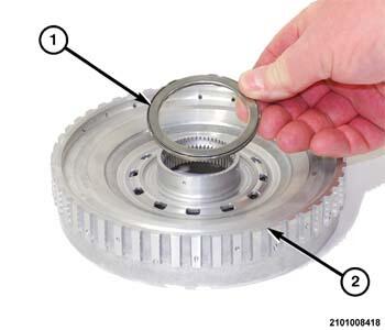
- Separate the E-clutch drum (1) from the E-clutch assembly (2).
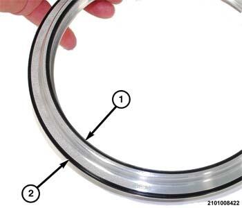
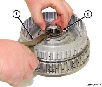
- Separate the thrust bearing (1) from the E-clutch assembly.
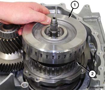
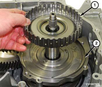
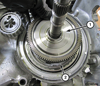
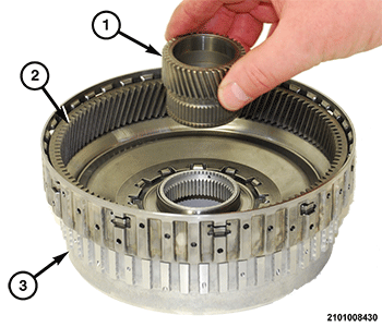
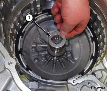
- Separate the E-clutch hub (1) from the output gear support (2).
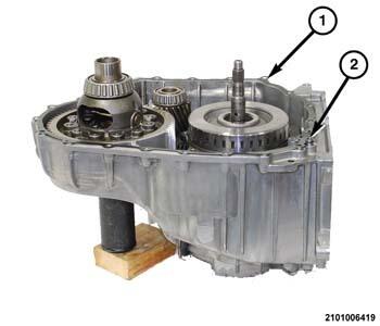
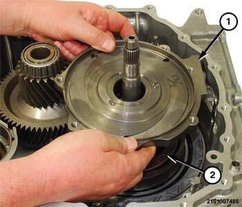
- Separate the output gear support (1) from the gear 4 planetary pinion carrier (2).
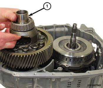
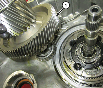
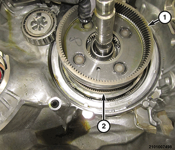
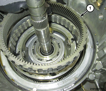
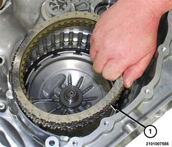
- Remove the transfer gear (1) from the transmission housing.
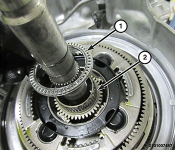
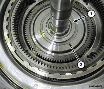
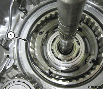
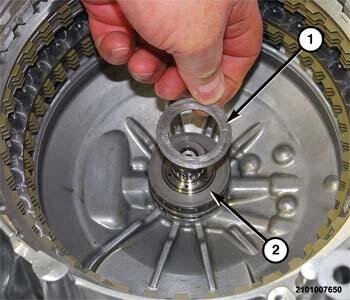
- Separate the roller type thrust bearing (1) from the sun gear 3 and 4 and Dog Clutch-F (2).
- Separate the sun gear 3 and 4 and Dog Clutch-F (1) from the gear 4 planetary pinion carrier.
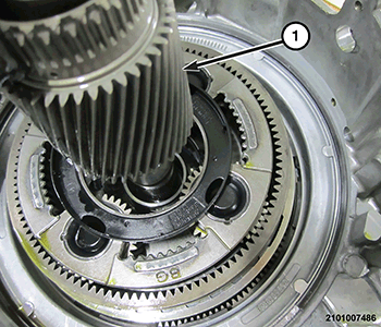
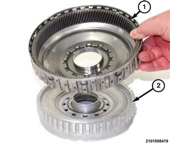
- Separate the gear 4 planetary pinion carrier (1) from the annulus gear 4.
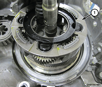
- Separate the annulus gear 4 (1) from the annulus gear 3 (2).
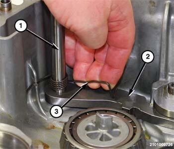
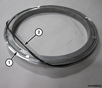
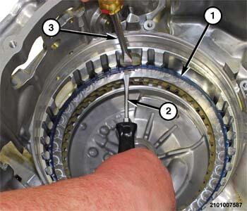
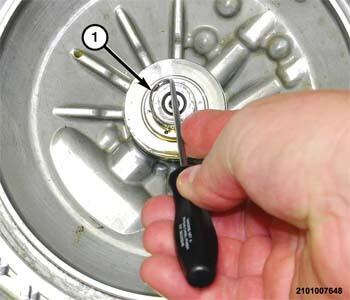
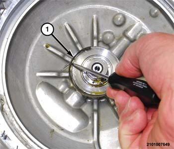
- Compress and release the park pawl (2) return spring (3).
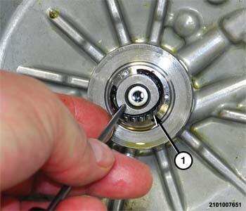
- Pull the reaction pin (1) from the park pawl (2).
- Separate the park pawl (2) from the park rod guide.NOTE:
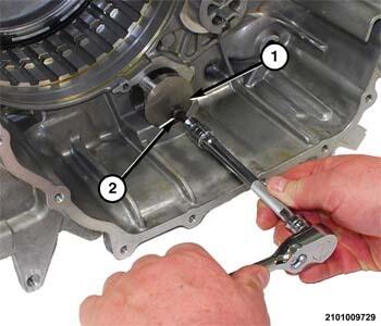
The park rod guide (1) can be removed without removing the park rod.
- Remove the park rod guide bolt (2) and the park rod guide (1).
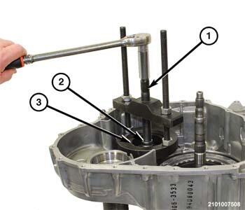
- Using the Press Puller (special tool #C-293-PA, Puller, Press) (1), Adapter Blocks (special tool #9738, Blocks, Adapter) (3) and a suitable socket as a plug (2), remove the transfer gear bearing cone from the transmission housing.
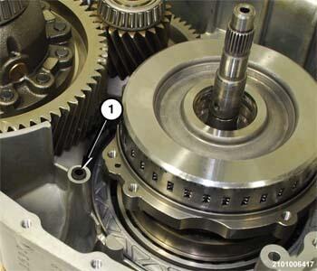
- Separate the trust bearing (1) from the annulus gear 1 planetary hub (2).
- Separate the annulus gear 1 planetary hub (1) from the carrier gear 1 and 2 (2).
- Separate the thrust bearing (1) from under the annulus gear 1 planetary hub (2).
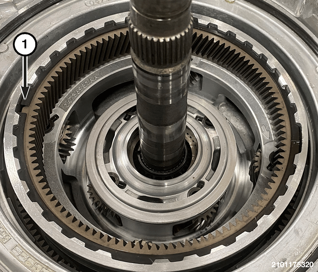
- Remove the snap-ring (1) for the annulus gear 3.
- Separate the annulus gear 3 (1) from the carrier gear 1 and 2.
- Remove the O-ring seal (1) from the carrier gear 1 and 2.
- Separate the carrier gear 1 and 2, annulus gear 2, D-clutch hub and input shaft assembly.
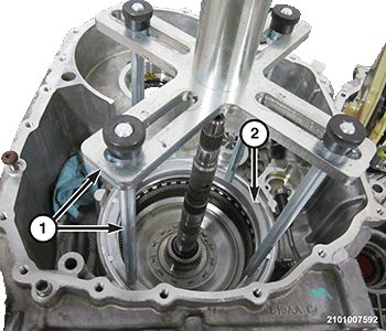
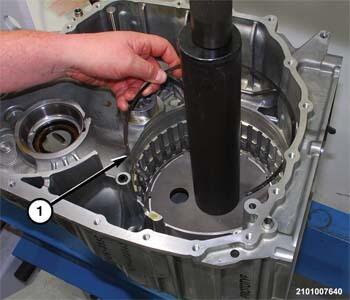
- Position the transmission housing on a suitable arbor press using wooden blocks for support.
- Using Pressing Tool (special tool #8901A, Pressing Tool) (1) (with pressure scale removed) and Pressing Tool Adapter (special tool #10428, Adapter, Pressing Tool), compress the belleville spring to gain access to the snap-ring holding the D-clutch piston retainer (2) into the transmission housing.NOTE:
The O-ring seal on the D-clutch piston retainer will hang up in the snap-ring groove during removal and will need to be pried out of the transmission housing.
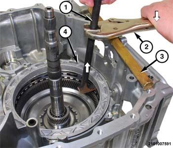
- Using a suitable pry-bar (1), vise-grip pliers (2), and a brass drift (3) coupled together, pry the D-clutch piston retainer (4) upward and out of the transmission housing.
- Remove the D-clutch piston (2) from the retainer (1).
- Remove the inner (1) and outer (2) lip seals from the D-clutch piston.
- Remove the O-ring seal (2) from the D-clutch piston retainer (1).
- Separate the belleville spring (1) from the transmission housing (2).
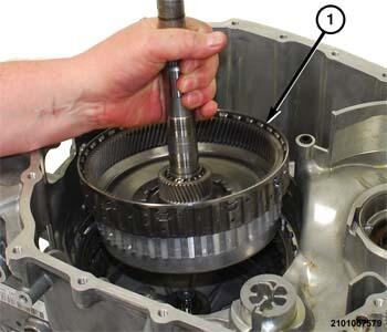
- Separate the annulus gear 2, D and C-clutch hub and input shaft assembly (1) from the transmission housing.
- Remove the annulus gear 2, D and C-clutch hub from the input shaft and B-clutch.
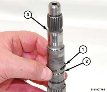
- Remove the seal-rings (1) from the lands (2) on the input shaft (3).NOTE:
Dog clutch A is permanently attached to the input shaft and cannot be disassembled.
- Using suitable snap-ring pliers (3), remove the snap-ring (2) holding the input shaft to the B-clutch (1) hub.
- Separate the input shaft/dog clutch A from the B-clutch (1) hub.
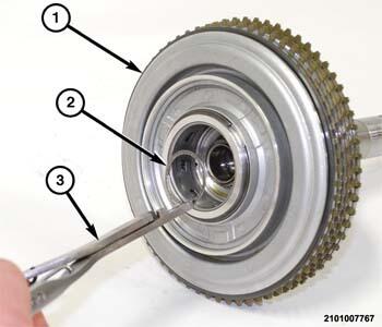
- Using a suitable tool (2), gently pry the thrust washer (1) from the C-clutch hub (3).
- Place the annulus gear 2, D and C-clutch hub (1) on tool Differential End Plug (special tool #9611, Plug, Differential End) (2) to hold the sun gear in position.
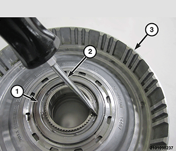
- Using a suitable snap-ring pliers (1), remove the snap-ring (2) holding the sun gear 1 to the annulus gear 2, D and C-clutch hub.
- Turn the annulus gear 2 (2), D and C-clutch hub (3) over and remove sun gear 1 (1).
- Separate the annulus gear 2, D-clutch hub (1) from the C-clutch hub (2).
- Separate the thrust bearing (1) from the C-clutch hub (2).
- Remove the thrust bearing (1) from the input shaft rear support.
- Remove the input shaft rear support selective thrust washer (1).
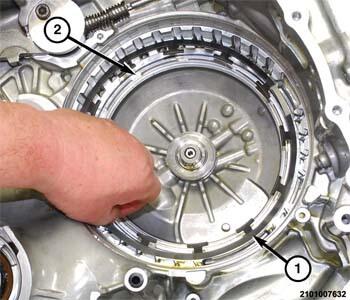
- Separate the D-clutch friction discs and steel plates (1) from the transmission housing.
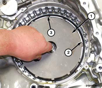
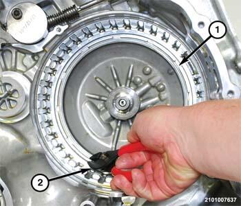
- Using two suitable screw drivers (2) and (3), lift the snap-ring (1) and pry it inward with the screwdriver (3) and out of from the groove in the transmission housing.
- Separate the C-clutch friction discs and steel plates (1) from the transmission housing.
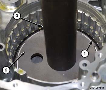
- Place the Spring Compressor (special tool #10504, Compressor, Spring) (1) over the C-clutch belleville spring at the bottom of the transmission housing.
- Place tool Bearing Installer (special tool #8228, Installer, Bearing) (3) over the input shaft support (tool 8901 with 10428 legs can also be used), compress the belleville spring to gain access to the stepped snap-ring (1).
- Using a suitable screw driver, remove the snap-ring (1) holding the C-clutch belleville spring in the transmission housing.
- Separate the C-clutch belleville spring (1) from the C-clutch piston (2).
- Using suitable pliers (2), remove the C-clutch piston (1) from the transmission housing.
- If overhaul is being performed, remove inner (1) and outer (2) seals from the C-clutch piston (3).
- Using a suitable hook tool, remove the inner seal-rings (1) from the input shaft support.
- Using a suitable hook tool, remove the outer seal-rings (1) from the input shaft support.
- Using a suitable hook tool, remove the split roller bearing (1) from the input shaft support.