Removal And Installation: Front: Installation
NOTE:
The following procedure is for replacement of an ineffective or damaged seat belt and retractor unit. The front retractor also includes a seat belt tensioner. If the front seat belt or retractor is ineffective or damaged, but the seat belt tensioner is not deployed, review the recommended procedures for Handling Non-Deployed Supplemental Restraints. Refer to STANDARD PROCEDURE . If the seat belt tensioner has been deployed, review the recommended procedures for Service After A Supplemental Restraint Deployment before removing the unit from the vehicle. Refer to STANDARD PROCEDURE .
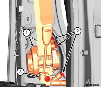
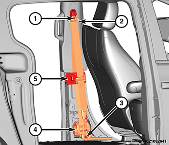
- Position the seat belt retractor unit (4) to the B-pillar by engaging the T-tab on the retractor bracket into the notch in the inner B-pillar and align the anchor tensioner with the mounting hole in the B-pillar.
- Install the screw (3) that secures the retractor bracket and anchor tensioner to the base of the inner B-pillar. Tighten the screw to the proper. Refer to TECHNICAL SPECIFICATIONS .
- Position the seat belt turning loop (2) onto the height adjuster. Be certain that the seat belt webbing between the retractor and the turning loop is not twisted.
- Install the nut (1) that secures the turning loop to the height adjuster. Tighten the nut to the proper. Refer to TECHNICAL SPECIFICATIONS .
- Install the retractor belt guide (5) to the inner B-pillar.
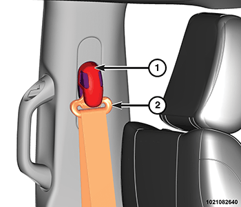
- Restore the cover (1) over the top of the seat belt turning loop (2).
- Connect the three body wire harness connectors (2) to the initiators for the two tensioners and the adaptive load limiter.
- Install the middle and lower trim onto the inside of the B-pillar. Refer to PANEL, B-PILLAR TRIM, LOWER, REMOVAL AND INSTALLATION .
- Be certain that the seat belt webbing between the turning loop and the lower anchor buckle is not twisted.
- Do not connect the negative battery cable at this time. The Supplemental Restraint System (SRS) Verification Test procedure should be performed following service of any SRS component. Refer to STANDARD PROCEDURE .