Theory Of Operation
Accelerator Pedal Position (APP) Sensor applications today use Induction/Hall Sensors (non-contact).
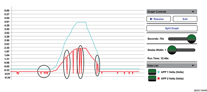
The Electronic Throttle Control (ETC) system uses two Accelerator Pedal Position (APP) Sensors to monitor the accelerator pedal position. The APP Sensors 1 and 2 are integrated into one assembly located at the pedal assembly. Each sensor has a 5 volt reference circuit, a low reference circuit, and a signal circuit. The Powertrain Control Module (PCM) reads the two signals individually and then compares the two signals as a redundant check of the pedal position. The APP 1 signal will fluctuate somewhere between 0 volts and 5.0 volts. The APP 2 signal will fluctuate somewhere between 0 volts and 2.5 volts. The fluctuation of the two sensors should move proportionately. When operating properly, the voltage reading of the APP 2 will always be approximately half of the voltage reading of the APP 1.
The signal for APP 2 is also used by the PCM for an internal ground check. This test runs a couple of times per second and is the reason why the APP 2 signal spikes to ground regularly during normal operation. If graphing the APP 1 and APP 2 signals for diagnostic purposes, view the figure below to see how the signals will look on a normally functioning APP system.