Diagnostic Test
- READ AND RECORD DTCS AND ENVIRONMENTAL DATA - ERASE DTCS AND CHECK FOR THE DTC TO RETURN
- With the scan tool, read DTCs in all Electronic Control Units (ECUs) and record on the repair order.
- For future reference, with the scan tool, run and save a vehicle Scan Report and all related recorded data.
- With the scan tool, erase all DTCs.
- Turn the ignition off for a minimum of 10.0 seconds.
- Turn the ignition on.
- Using the When Monitored and Set Conditions above and recorded data, operate the vehicle in the conditions that set the DTC.
- With the scan tool, read DTCs.
Did the DTC return?
Yes
- Go To 2
No
- Perform the INTERMITTENT CONDITION diagnostic procedure. Refer to INTERMITTENT CONDITION .
- CHECK THE VVT EXHAUST SOLENOID 2/2 CONNECTOR AND TERMINALS
- Turn the ignition off.
- Check the VVT Exhaust Solenoid 2/2 harness connector for proper connection at the VVT Exhaust Solenoid 2/2.
- Verify that the connector is completely plugged in and properly locked prior to disconnecting.
- Disconnect the VVT Exhaust Solenoid 2/2 harness connector and check for any pushed out, damaged or spread terminals.
Were any issues found with the connector or terminals?
Yes
- Repair the damaged terminal or properly connect and lock the VVT Exhaust Solenoid 2/2 harness connector and retest for DTCs.
- Perform the POWERTRAIN VERIFICATION TEST. Refer to POWERTRAIN VERIFICATION TEST .
No
- Go To 3
- CHECK THE VVT EXHAUST SOLENOID 2/2 (K277) CONTROL CIRCUIT FOR A SHORT TO VOLTAGE
- Turn the ignition on.
- Measure the voltage on the VVT Exhaust Solenoid 2/2 (K277) Control circuit at the VVT Exhaust Solenoid 2/2 harness connector.NOTE:
There should be no voltage present unless you have a short to voltage, except for a brief period immediately after turning ignition on.
Is there any voltage present?
Yes
- Repair the VVT Exhaust Solenoid 2/2 (K277) Control circuit for a short to voltage.
- Perform the POWERTRAIN VERIFICATION TEST. Refer to POWERTRAIN VERIFICATION TEST .
No
- Go To 4
- CHECK THE VVT EXHAUST SOLENOID 2/2 (K277) CONTROL CIRCUIT FOR A SHORT TO GROUND
- Turn the ignition off.
- Disconnect the PCM C2 harness connector.
- Check for continuity between ground and the VVT Exhaust Solenoid 2/2 (K277) Control circuit at the VVT Exhaust Solenoid 2/2 harness connector.
Is there continuity between ground and the VVT Exhaust Solenoid 2/2 (K277) Control circuit?
Yes
- Repair the VVT Exhaust Solenoid 2/2 (K277) Control circuit for a short to ground.
- Perform the POWERTRAIN VERIFICATION TEST. Refer to POWERTRAIN VERIFICATION TEST .
No
- Go To 5
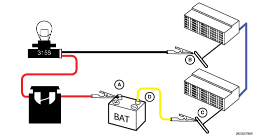
- ISOLATE AND LOAD TEST THE VVT EXHAUST SOLENOID 2/2 (K277) CONTROL CIRCUIT TO CHECK FOR HIGH RESISTANCE CAUTION:
Do not load test any circuits with components still connected to the circuit.
- Isolate and load test the VVT Exhaust Solenoid 2/2 (K277) Control circuit.NOTE:
The bulb on the load test tool should be illuminated and bright if there is no resistance in the circuit. Compare the brightness of the bulb in the load test tool to that of a direct connection to Battery.
Is the load test bulb illuminated and bright?
Yes
- Go To 6
No
- Repair the VVT Exhaust Solenoid 2/2 (K277) Control circuit for an open or high resistance.
- Perform the POWERTRAIN VERIFICATION TEST. Refer to POWERTRAIN VERIFICATION TEST .
- Isolate and load test the VVT Exhaust Solenoid 2/2 (K277) Control circuit.
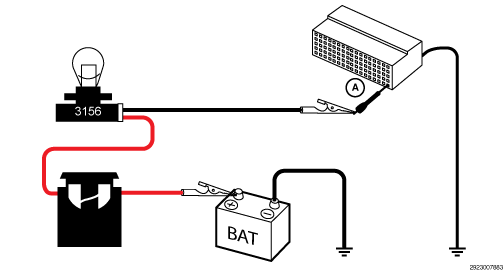
- CHECK THE VVT EXHAUST SOLENOID 2/2 (Z904) GROUND CIRCUIT FOR HIGH RESISTANCE BY LOAD TESTING THE CIRCUIT NOTE:
Read the CIRCUIT LOAD TESTING PROCEDURE for information on building a simple load test tool and for additional load testing information and alternative methods of load testing or voltage drop testing a circuit. Refer to CIRCUIT LOAD TESTING PROCEDURES .
CAUTION:Do not load test any circuits with components still connected to the circuit.
- Load test the VVT Exhaust Solenoid 2/2 (Z904) Ground circuit at the Intake Camshaft 2/2 VVT Solenoid harness connector (A). Note:
refer to the diagram below.NOTE:
The bulb on the load test tool should be illuminated and bright if there is no resistance in the circuitry. Compare the brightness of the bulb in the load test tool to that of a direct connection to Battery.
Is the load test bulb illuminated and bright?
Yes
- Go To 7
No
- Repair the VVT Exhaust Solenoid 2/2 (Z904) Ground circuit for an open or high resistance.
- Perform the POWERTRAIN VERIFICATION TEST. Refer to POWERTRAIN VERIFICATION TEST .
- Load test the VVT Exhaust Solenoid 2/2 (Z904) Ground circuit at the Intake Camshaft 2/2 VVT Solenoid harness connector (A). Note:
refer to the diagram below.
- ACTUATE AND CHECK THE OPERATION OF THE VVT EXHAUST SOLENOID 2/2 DRIVER
- Reconnect the PCM C2 harness connector.
- Turn the ignition on.
- Using a 12-volt test light connected to ground, probe the VVT Exhaust Solenoid 2/2 (K277) Control circuit in the VVT Exhaust Solenoid 2/2 harness connector.NOTE:
The PCM will command the solenoid ON briefly after the ignition is turned on. This is a normal condition. The test light will illuminate briefly and then turn off and stay off if there is not a short to voltage.
- With the scan tool, actuate the VVT Exhaust Solenoid 2/2 Control to the highest duty cycle (80%) position.NOTE:
The test light should be illuminated and bright. Compare the brightness to that of a direct connection to the Battery.
Is the test light illuminated and bright?
Yes
- Replace the VVT Exhaust Solenoid 2/2 in accordance with the Service Information. Refer to SOLENOID, VARIABLE VALVE TIMING, REMOVAL AND INSTALLATION .
- Perform the POWERTRAIN VERIFICATION TEST. Refer to POWERTRAIN VERIFICATION TEST .
No
- Go To 8
- CHECK RELATED PCM AND COMPONENT CONNECTIONS
- Perform any Service Bulletins that apply.
- Disconnect all PCM harness connectors.
- Disconnect all related in-line harness connections (if equipped).
- Disconnect the related component harness connectors.
- Inspect harness connectors, component connectors, and all male and female terminals for the following conditions:
- Proper connector installation.
- Damaged connector locks.
- Corrosion.
- Other signs of water intrusion.
- Weather seal damage (if equipped).
- Bent terminals.
- Overheating due to a poor connection (terminal may be discolored due to excessive current draw).
- Terminals that have been pushed back into the connector cavity.
- Check for spread terminals and verify proper terminal tension.
Repair any conditions that are found.
- Reconnect all PCM harness connectors. Be certain that all harness connectors are fully seated and the connector locks are fully engaged.
- Reconnect all in-line harness connectors (if equipped). Be certain that all connectors are fully seated and the connector locks are fully engaged.
- Reconnect all related component harness connectors. Be certain that all connectors are fully seated and the connector locks are fully engaged.
- With the scan tool, erase DTCs.
- Test drive or operate the vehicle in accordance with the when monitored and set conditions.
- With the scan tool, read DTCs.
Did the DTC return?
Yes
- Replace and program the Powertrain Control Module (PCM) in accordance with the Service Information. Refer to MODULE, POWERTRAIN CONTROL (PCM), REMOVAL AND INSTALLATION .
- Perform the POWERTRAIN VERIFICATION TEST. Refer to POWERTRAIN VERIFICATION TEST .
No
- The wiring or poor connection problem has been repaired.
- Perform the POWERTRAIN VERIFICATION TEST. Refer to POWERTRAIN VERIFICATION TEST .