Right Cylinder Head Cover: Installation
The magnetic timing wheels must not come in contact with magnets (pickup tools, trays, ect.) or any other strong magnetic field. This will destroy the timing wheels ability to correctly relay camshaft position to the camshaft position sensor.
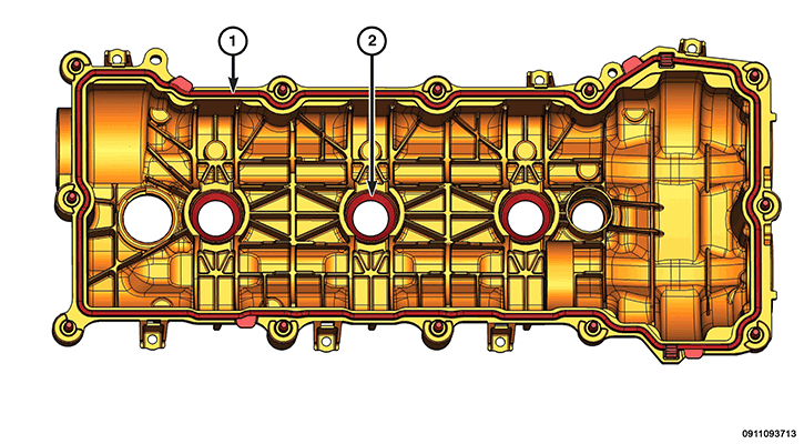
- Install the NEW cylinder head cover gasket (1).
- If required, install new spark plug tube seals (2), in the cylinder head cover.
- Clean the engine timing cover, cylinder head and cylinder head cover mating surfaces with isopropyl alcohol in preparation for sealant application.CAUTION:
Engine assembly requires the use of a unique sealant that is compatible with engine oil. Using a sealant other than Mopar® Threebond Engine RTV Sealant may result in engine fluid leakage.
CAUTION:Following the application of Mopar® Threebond Engine RTV Sealant to the gasket surfaces, the components must be assembled within 10 minutes and the attaching fasteners must be tightened to specification within 45 minutes. Prolonged exposure to the air prior to assembly may result in engine fluid leakage.
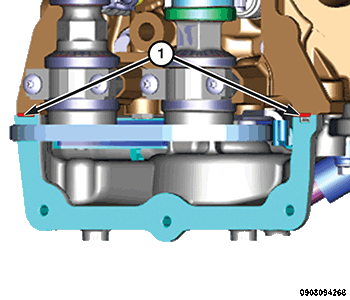
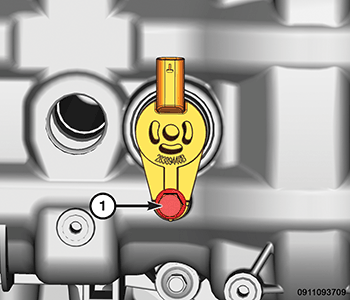
- Apply a 11 mm dollop of Mopar® Threebond Engine RTV Sealant to the two engine timing cover to cylinder head T-joints (1).
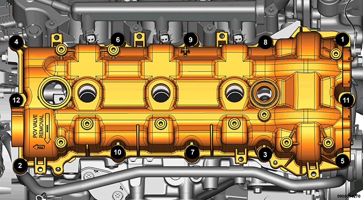
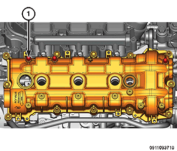
- Align the locator pins (1) to the cylinder head and install the cylinder head cover.
- Tighten the cylinder head cover bolts and double ended studs in the sequence shown in illustration to 12 N.m (106 in. lbs.).
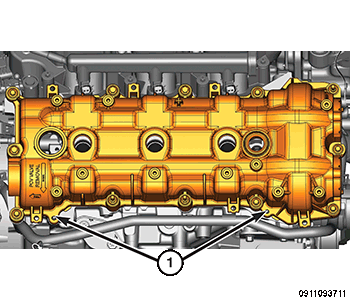
- Install and securely tighten the resonator and fuel vapor tube mounts (1) onto the cylinder head cover.
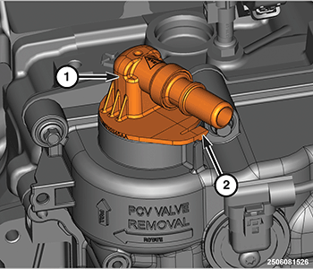
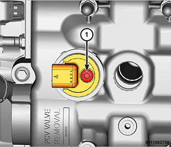
- Install the PCV valve (1) and verify that the locking tab (2) is in position.
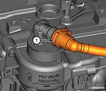
- Secure the PCV valve hose (1) to the PCV valve.
- Install the Variable Valve Lift (VVL) solenoid (1) into right cylinder head cover. Refer to SOLENOID, VARIABLE VALVE LIFT, REMOVAL AND INSTALLATION .
- Install the Camshaft Position (CMP) sensor (1). Refer to SENSOR, CAMSHAFT POSITION, REMOVAL AND INSTALLATION
.
- If removed, install the spark plugs. Refer to SPARK PLUG, REMOVAL AND INSTALLATION .
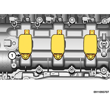
- Install the right side ignition coils (1). Refer to COIL, IGNITION, REMOVAL AND INSTALLATION
.
- Install the injector (1) and ignition (2) wire harness retainers and position the wire harness to the cylinder head cover.
- Connect the wire harness connector (1) to the right side camshaft position sensor.
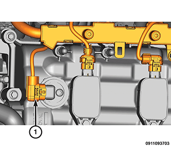
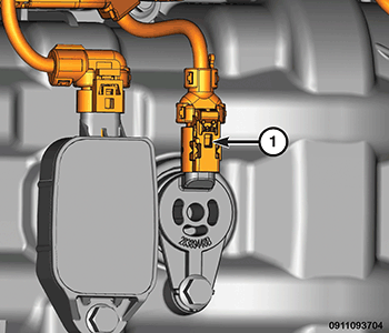
- Connect the VVL solenoid wire harness connector (1).
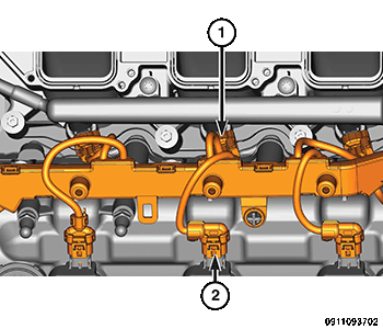
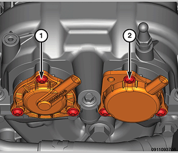
- Refer to the markings made at disassembly and install the variable valve timing solenoids (1 and 2) in their original locations.
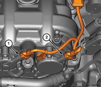
- Connect the wire harness connectors (1 and 2) to the variable valve timing solenoids on the right cylinder head.
- Engage the wire harness retainers to the right cylinder head cover.
- Install the heater hose assembly onto the right side cylinder head cover.
- Install the air cleaner body. Refer to BODY, AIR CLEANER, REMOVAL AND INSTALLATION .
- Install the engine cover and bracket. Refer to COVER, ENGINE, REMOVAL AND INSTALLATION .
- Connect the negative battery cable.
The Cam/Crank Variation Relearn procedure must be performed using the scan tool anytime there has been a repair/replacement made to a powertrain system, for example: flywheel, valvetrain, camshaft and/or crankshaft sensors or components.