Removal And Installation: Left: Installation
multimedia:A supplement to the article is available.
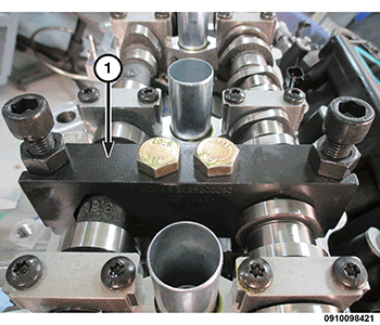
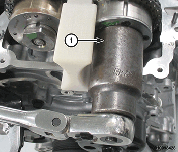
- The Timing Chain Tensioner Holder and Camshaft Holder (1) should still be in place as installed during the removal procedure. If required, the Timing Chain Tensioner Holder and Camshaft Holder can be installed by repeating the steps within the removal procedure. Refer to ASSEMBLY, VARIABLE VALVE TIMING, PHASER / OIL CONTROL VALVE, REMOVAL AND INSTALLATION .
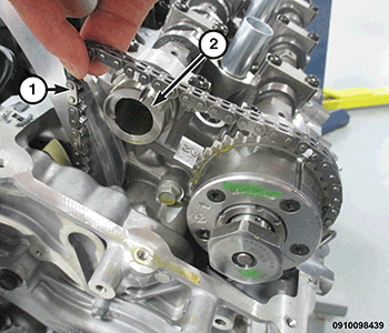
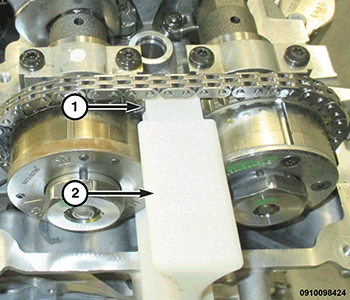
- Route the timing chain (1) around the left intake cam phaser while aligning the paint mark with the phaser timing mark. Press the left intake cam phaser onto the intake camshaft (2). Install and hand tighten the oil control valve.
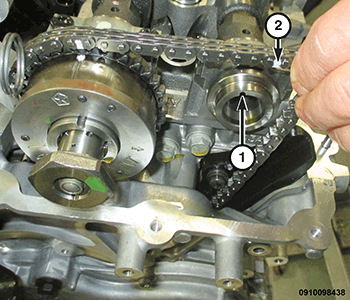
- While maintaining this alignment, route the timing chain (2) around the exhaust cam phaser so that the paint mark is aligned with the phaser timing mark. Press the exhaust cam phaser onto the exhaust cam (1), install and hand tighten the oil control valve.
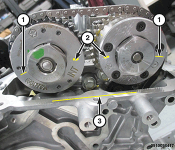
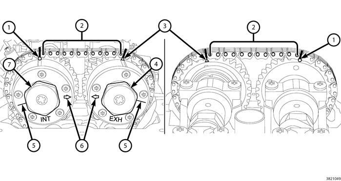
- The SCRIBE LINES
(1) on the cam phasers should face away from each other and the ARROWS
(2) should point toward each other and be parallel to the cylinder head cover mounting surface (3). There should be twelve chain pins BETWEEN
the exhaust cam phaser mark and the intake cam phaser mark.
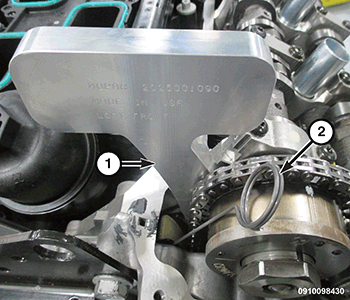
- Install the (special tool #2025101090, Holder, Camshaft Phaser - Left-Front Cyl Head) (2) against the cylinder head cover mounting surface with the tool number facing up, between the intake and exhaust phasers (1).
- Tighten the intake oil control valve (1) to the proper torque specification. Refer to TECHNICAL SPECIFICATIONS .
- Tighten the exhaust oil control valve (1) to the proper torque specification. Refer to TECHNICAL SPECIFICATIONS .
- Remove the (special tool #2025101090, Holder, Camshaft Phaser - Left-Front Cyl Head) (2).
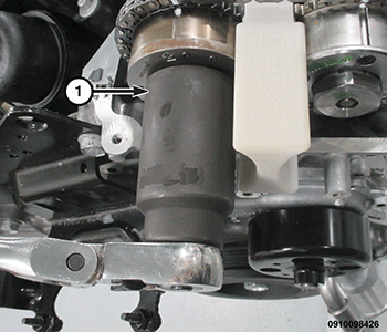
- Remove the (special tool #2025001090, Holder, Timing Chain Tensioner, Left-Front) (1).
- Remove the (special tool #2025200090, Holder, Camshaft) (1).
- Rotate the crankshaft clockwise two complete revolutions stopping when the right side number one cylinder piston is again positioned at top-dead-center on the exhaust stroke. To assure correct engine timing, verify the following;
- The indicator dial is set to ZERO when the right side number one cylinder piston is positioned at top-dead-center on the exhaust stroke.
- The SCRIBE LINES (5) on the left side cam phasers face away from each other.
- The ARROWS (6) on the left side cam phasers point toward each other and are parallel to the cylinder head cover mounting surface.
- There are twelve chain pins (2) BETWEEN the exhaust cam phaser mark (3) and the intake cam phaser mark (1).
- If the engine timing is not correct, repeat this procedure.
- Install the left cylinder head cover. Refer to COVER(S), CYLINDER HEAD, REMOVAL AND INSTALLATION .
- Install the right side spark plugs. Refer to SPARK PLUG, REMOVAL AND INSTALLATION .
- Start the engine and perform the following Powertrain Verification Tests. Refer to POWERTRAIN VERIFICATION TEST
.
- Cam/Crank Variation Relearn
- Target Coefficient Relearn
NOTE:
Following the first restart after a DTC driven phaser replacement, clear all DTCs and verify that subsequent restarts do not set any additional codes for any DTCs that reset. Refer to DTC INDEX .