Upper Intake Manifold: Installation
NOTE:
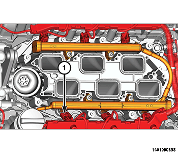
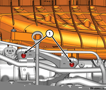
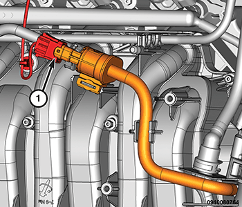
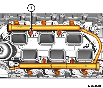
Prior to installing the upper intake manifold, verify that the four fuel rail bolts (1) were not inadvertently loosened. If loosened, the bolts must installed to the proper specification. Refer to RAIL, FUEL, REMOVAL AND INSTALLATION .
- Clean and inspect the upper seals of the lower intake manifold assembly, and replace only if necessary.
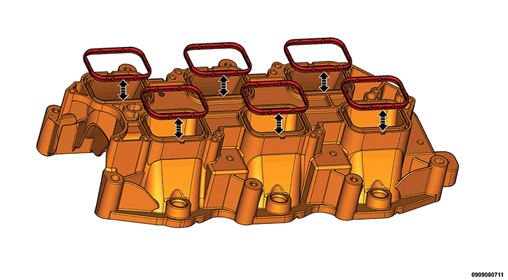
- Clean and inspect the sealing surfaces. Install the upper to lower intake manifold gaskets.
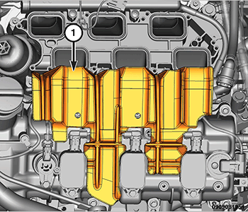
- Make sure the fuel injectors and wiring harnesses (1) are in the correct position so that they do not interfere with the upper intake manifold installation.
- If removed, install the insulator (1) on top of the LH cylinder head cover.
- Lift and hold the eight upper intake attaching bolts clear of the mating surface. Back the bolts out slightly or if required, use an elastic band to hold the bolts clear of the mating surface.
- Position the upper intake manifold onto the lower intake manifold so that the two locating posts on the upper intake manifold align with corresponding holes in the lower intake manifold.
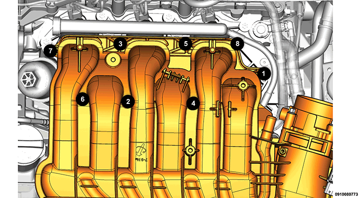
- Install the eight upper intake manifold attaching bolts. Tighten the bolts in the sequence shown in illustration to the proper torque specification. Refer to TECHNICAL SPECIFICATIONS .
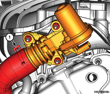
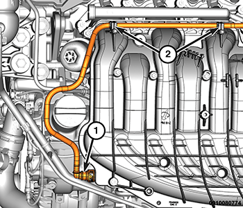
- Connect the EGR cooler hose (1) to the EGR valve.
- Connect the EGR valve wire harness connector.
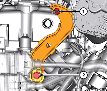
- Install the two upper intake manifold support bracket bolts (1) and tighten to the proper torque specification. Refer to TECHNICAL SPECIFICATIONS .
- Position the support bracket onto the intake manifold stud and tighten the lower mounting bolt (2) to the proper torque specification. Refer to TECHNICAL SPECIFICATIONS .
- Install the support bracket nut (1) and tighten the nut to the proper torque specification. Refer to TECHNICAL SPECIFICATIONS .
- Install the electric vacuum pump and bracket. Refer to PUMP, VACUUM, REMOVAL AND INSTALLATION
.
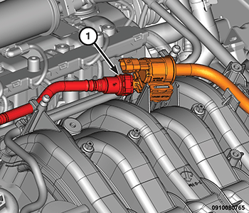
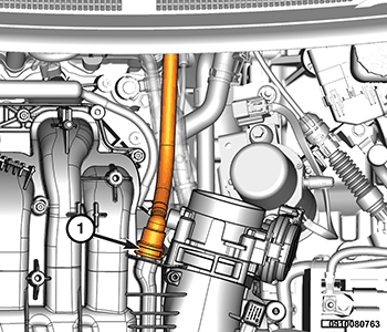
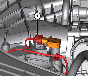
- Connect the vapor purge line (1).
- Connect the evaporative purge solenoid wire harness connector (1) and attach the wire harness retainer to the manifold.
- Connect the brake booster (1) and attach the hose (2) to the manifold.
- Connect the Positive Crankcase Ventilation (PCV) (1).
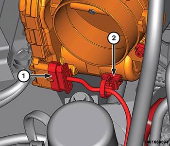
- Connect the Electronic Throttle Control (ETC) wire harness connectors (1) and attach the wire harness retainer (2) to the ETC.
- Connect the Manifold Absolute Pressure (MAP) sensor (1) wire harness connectors and attach the wire harness retainer to the manifold.
- Install the air cleaner intake resonator. Refer to RESONATOR, AIR CLEANER, REMOVAL AND INSTALLATION .
- Connect the negative battery cable.
- Install the engine cover. Refer to COVER, ENGINE, REMOVAL AND INSTALLATION .