Performing A Voltage Drop Test Across A Circuit
TESTING FOR THE VOLTAGE DROP ACROSS AN ENTIRE CIRCUIT
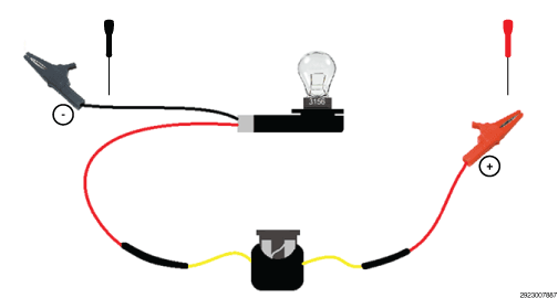
The load tool illustrated in this procedure will be used as our simple series circuit for example purposes. In this example, assume that the red alligator clip is a B+ (12.6 volt) source and the black alligator clip is attached to chassis ground to provide a complete circuit. The load in this case is a 3156 bulb with 6.0 Ohms of resistance when energized but could be a motor, solenoid, heater, relay control, etc.
- Use a DVOM set to measure DC voltage.
- A voltage drop test should be performed on a component that is being energized. Operate the component that is being controlled now to properly diagnose the circuitry.
- To check the voltage drop across the entire B+ circuit , back probe and connect the positive lead of a DVOM at the (source) red alligator clip. Back probe and connect the negative lead of the DVOM to the B+ circuit at the bulb connector. Use appropriate back probe tools to prevent damaging component connectors.
- To check the voltage drop across the entire ground circuit
, back probe and connect the positive lead of a DVOM to the ground circuit at the bulb connector. Connect the negative lead of the DVOM at the (chassis ground) black alligator clip. Use appropriate back probe tools to prevent damaging component connectors.NOTE:
If there is no resistance in either of the circuits, the reading on the DVOM should measure 0 volts. Considering that the 3156 bulb has 6.0 Ohms of resistance when energized, if either circuit had as little as 2.0 Ohms of resistance the DVOM would read approximately 3.15 volts when measuring the voltage drop of that circuit.
- Monitor the voltage readings.
- The voltmeter will show the difference in voltage between the two points.
Is the voltage drop within an acceptable amount in the circuits, based on the resistance of the component?
Yes
- At this time the circuits are functioning properly. Measure the voltage in the circuits and wiggle the wiring harness and connectors to check for an intermittent condition. If there is no voltage drop on either circuit, check the voltage drop across the component. If the measurement is equal to source voltage and the component is inoperative, the component is faulty.
No
- Repair the circuit that had an excessive voltage drop.
- Use the wiring diagram as a guide to trace the circuit and look for any in-line connectors where the excessive resistance may occur.
- Look for any chafed, pierced, pinched, or partially broken wires.
- Look for broken, bent, pushed out or corroded terminals. Verify that there is good pin to terminal contact in the related wire harness connectors.