Removal And Installation: Inboard: Installation
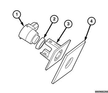
The park assist sensors (1) and the resilient sensor spacers (2) (also known as decoupling rings or O-rings) are each available for separate service replacement. The sensor brackets (3) are bonded to and integral to the inside surface of the bumper fascia (4).
In vehicles equipped with the optional Parallel and Perpendicular Park Assist (PPPA) option only, the park assist sensors located in the outward facing ends of both the front and rear bumper fascias are unique and must not be interchanged with any other forward or rearward facing park assist sensor.
- Engage the O-ring spacer (2) around the circumference of the sensor membrane protrusion.NOTE:
Production and all service replacement O-ring spacers are tapered. The wide side (base) of the O-ring should be seated against the sensor housing and the narrow side should be oriented toward the outer surface of the sensor membrane and the rear fascia.
- From behind the fascia, align and insert the park assist sensor (1) into the sensor bracket (3) on the inside surface of the bumper fascia (4) until the bracket latch features are fully engaged over the latch tabs of the sensor.NOTE:
Be certain that each sensor membrane is properly centered in the openings of the bumper fascia and that the resilient O-ring spacers are not pinched. Improper centering or pinched O-rings can be detrimental to proper park assist sensor operation. Be certain that the sensor membrane is flush with the outer surface of the bumper fascia.
- Connect the wire harness connector to the sensor connector receptacle.
- If removed install the hands free liftgate module. Refer to MODULE, HANDS FREE LIFTGATE, REMOVAL AND INSTALLATION .
- Install the appropriate fascia. For the front fascia. Refer to FASCIA, FRONT, REMOVAL AND INSTALLATION . For the rear fascia. Refer to FASCIA, REAR, REMOVAL AND INSTALLATION .
- Connect the negative cable to the battery. If equipped with an Intelligent Battery Sensor (IBS), reconnect the IBS connector.