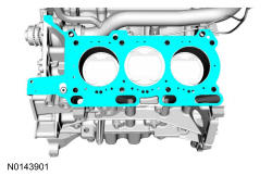
Cylinder Head - LH
WARNING: This page is about a different variant/trim than selected.
Material
| Item | Specification |
| Motorcraft ® SAE 5W-30 Premium Synthetic Blend Motor Oil (US); Motorcraft ® SAE 5W-30 Super Premium Motor Oil (Canada) XO-5W30-QSP (US); CXO-5W30-LSP12 (Canada) | WSS-M2C946-A |
NOTE:
During engine repair procedures, cleanliness is extremely important. Any foreign material, including any material created while cleaning gasket surfaces that enters the oil passages, coolant passages or the oil pan, may cause engine failure.
NOTE:
Whenever turbocharger air intake system components are removed, always cover open ports to protect from debris. It is important that no foreign material enter the system. The turbocharger compressor vanes are susceptible to damage from even small particles. All components should be inspected and cleaned, if necessary, prior to installation or reassembly.
- 2.
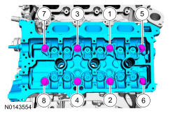
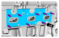
Install a new gasket, the LH cylinder head and 8 new bolts. Tighten in the sequence shown in 5 stages:- Stage 1: Tighten to 20 Nm (177 lb-in).
- Stage 2: Tighten to 35 Nm (26 lb-ft).
- Stage 3: Tighten 90 degrees.
- Stage 4: Tighten 90 degrees.
- Stage 5: Tighten 45 degrees.
- 4.
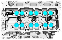
Install the valve tappets.
NOTE:
Coat the valve tappets with clean engine oil prior to installation.
NOTE:
The valve tappets must be installed in their original positions.

- 7.
Install the RH cylinder block drain plug or, if equipped, the block heater.- Tighten the cylinder block drain plug to 10 Nm (89 lb-in) plus an additional 720 degrees.
- Tighten the block heater to 40 Nm (30 lb-ft).
- 10.
Install the LH cylinder block drain plug.- Tighten to 16 Nm (142 lb-in) plus an additional 180 degrees.
- 12.
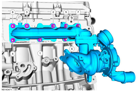
Install the LH exhaust manifold and turbocharger assembly and 8 new nuts. Tighten the nuts in 2 stages in the sequence shown:- Stage 1: Tighten to 15 Nm (133 lb-in).
- Stage 2: Tighten to 20 Nm (177 lb-in).
NOTE:
Failure to tighten the exhaust manifold nuts to specification a second time will cause the exhaust manifold to develop an exhaust leak.
 Courtesy of FORD MOTOR CO.
- 13.
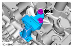
Install the upper turbocharger bracket-to-cylinder block and the 2 bolts.- Do not tighten the bolts at this time.
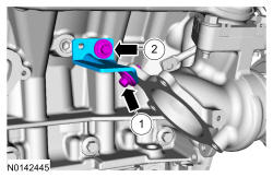
- 14.
Install the lower turbocharger-to-cylinder block bracket and the 2 bolts.- Do not tighten the bolts at this time.
NOTE:
The next 4 steps must be performed in order or damage to the turbocharger may occur.
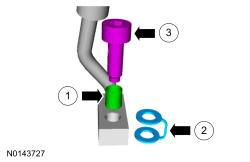
- 19.
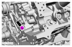
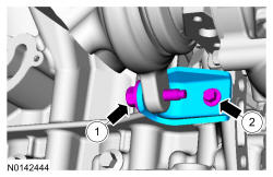
Install the oil supply tube filter, washer and bolt.- 1.
Install a new filter.
- 2.
Install a new sealing washer.
- 3.
Install the bolt.
- 1.
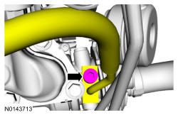
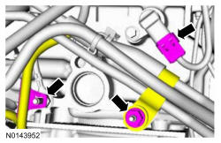
- 22.
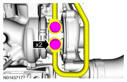
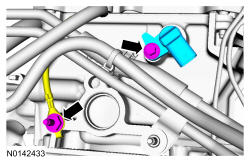
Using 2 new sealing washers, install the 2 LH turbocharger coolant tubes and the banjo bolts.- Tighten to 40 Nm (30 lb-ft).
- 23.
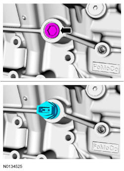
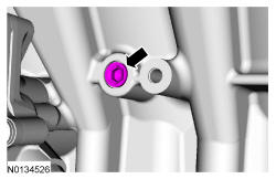
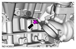
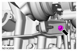
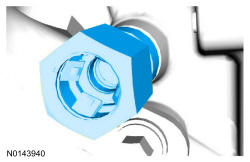
If necessary, install the LH cylinder head turbocharger oil supply quick connect fitting.- Tighten to 8 Nm (71 lb-in) plus an additional 540 degrees.
- 24.
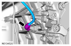
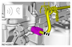
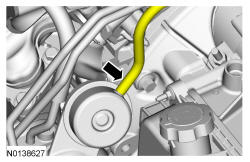
Install the LH oil supply tube into the quick connect fitting. REFER to Fuel System General Information .
NOTE:
Listen for audible click when installing the oil supply tube into the quick connect fitting.
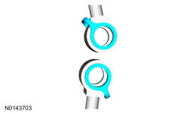
- 26.
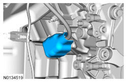
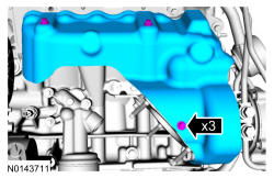
Install 2 new O-ring seals and new gasket on the oil return tube.
NOTE:
Lubricate the oil pan bore and O-ring seals with clean engine oil.
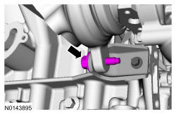
- 27.
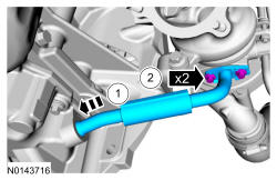
Install the LH turbocharger oil return tube in the oil pan and install the 2 bolts.- Tighten to 10 Nm (89 lb-in).
NOTE:
Lubricate the oil pan bore with clean engine oil.
- 28.
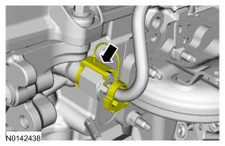
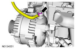
Connect the turbocharger wastegate regulating valve hose to the LH turbocharger assembly.
NOTE:
Make sure the turbocharger wastegate regulating valve hose does not contact the exhaust manifold heat shield.
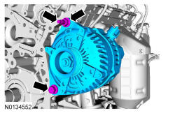
- 30.
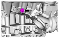
Install the stud, generator and the nut and bolt.- Tighten the stud to 8 Nm (71 lb-in).
- Tighten the nut and bolt to 47 Nm (35 lb-ft).
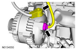
- 33.
Install LH CMP sensor and the bolt and install the ground wire and the stud bolt.- Tighten to 10 Nm (89 lb-in).
- 34.
Connect the LH CMP sensor electrical connector and install the coolant tube retainer nut.- Tighten to 10 Nm (89 lb-in).
- Attach the wiring harness retainer.
- 35.
Install the LH camshafts. Refer to Camshaft .
- 36.
Install the fuel rails. FUEL CHARGING AND CONTROLS - 3.5L GTDI .