Pinpoint Test J : Transmission Range Sensor
- J1 RETRIEVE AND RECORD ALL DTCS
- Using the diagnostic scan tool, retrieve all DTCs.
Are DTCs P0706, P0707, P0708, P0709, P1702, P1705 and/or P1921 present?
Yes For DTCs P0706, P0707, P0708, P0709, P1702 and/or P1921, GO to J2. For DTC P1705, GO to J8. No GO to Symptom Chart . - J2 CHECK THE TR SENSOR CIRCUITS FOR POWER
- Ignition OFF.
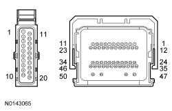
- Disconnect: Transmission Vehicle Harness C168 .
- Inspect the connector for damaged or pushed-out terminals, corrosion, loose wires and missing or damaged seals.
- Ignition ON.
- Measure the voltage
between.
Positive Lead Negative Lead Pin Circuit Pin Circuit C168-4 VET29 (VT/WH) - Ground C168-5 VET30 (YE) - Ground C168-7 VET32 (VT) - Ground
Is the voltage greater than 10 volts?
Yes GO to J3. No GO to J5. - J3 CHECK THE TR SENSOR CIRCUITS FOR POWER
- Ignition OFF.
- Disconnect: Transmission Vehicle Harness C168 .
- Inspect the connector for damaged or pushed-out terminals, corrosion, loose wires and missing or damaged seals.
- Ignition ON.
- Measure the voltage
between.
Positive Lead Negative Lead Pin Circuit Pin Circuit C168-6 VET31 (BU/OG) - Ground
Is the voltage approximately 5 volts?
Yes GO to J4. No GO to J5. - J4 CHECK THE TR SENSOR GROUND CIRCUIT
- Measure the voltage
between.
Positive Lead Negative Lead Pin Circuit Pin Circuit C168-4 VET29 (VT/WH) C168-8 RET24 (BN/BU)
Is the voltage less than 10 volts?
Yes REPAIR the circuit. No GO to J7. - Measure the voltage
between.
- J5 CHECK THE TR SENSOR CIRCUITS FOR AN OPEN
- Ignition OFF.
- Disconnect: PCM C175T .
- Inspect the connector for damaged or pushed-out terminals, corrosion, loose wires and missing or damaged seals.
- Measure the resistance
between.
Positive Lead Negative Lead Pin Circuit Pin Circuit C168-4 VET29 (VT/WH) C175T-26 VET29 (VT/WH) C168-5 VET30 (YE) C175T-27 VET30 (YE) C168-6 VET31 (BU/OG) C175T-30 VET31 (BU/OG) C168-7 VET32 (VT) C175T-17 VET32 (VT) C168-8 RET24 (BN/BU) C175T-36 RET24 (BN/BU)
Is the resistance greater than 3 ohms?
Yes REPAIR the circuit. No GO to J6. - J6 CHECK THE TR SENSOR CIRCUIT FOR A SHORT TO GROUND
- Measure the resistance
between.
Positive Lead Negative Lead Pin Circuit Pin Circuit C168-4 VET29 (VT/WH) - Ground C168-5 VET30 (YE) - Ground C168-6 VET31 (BU/OG) - Ground C168-7 VET32 (VT) - Ground
Is the resistance less than 3 ohms?
Yes REPAIR the circuit. No INSTALL a new PCM. REFER to Electronic Engine Controls . PERFORM the Solenoid Body Strategy Data Download procedure. REFER to Solenoid Body Strategy Download . - Measure the resistance
between.
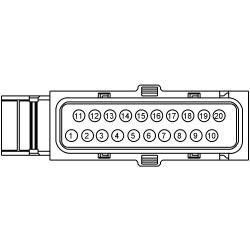
- J7 CHECK THE TR SENSOR SOLENOID BODY ASSEMBLY
- Remove the main control cover. For 3.5L Ti-VCT, REFER to Main Control Cover - 3.5L Ti-VCT .
- Measure the component side resistance
between.
Positive Lead Negative Lead Pin Circuit Pin Circuit Function 4 - 5 Transmission Range (TR) 1 5 - 4 TR 2 6 - 3 TR 3 7 - 2 TR 4 8 - 1 TR Ground
Is the resistance less than 0.5 ohms?
Yes REPLACE the TR sensor. REFER to Transmission Range (TR) Sensor . No INSTALL a new solenoid body assembly. REFER to Solenoid Body Assembly . PERFORM the Solenoid Body Strategy Data Download procedure. REFER to Solenoid Body Strategy Download . PERFORM the Solenoid Body Strategy Drive Cycle, REFER to Solenoid Body Strategy Drive Cycle . - J8 ON DEMAND SELF-TEST
- Check to make sure the transmission harness connector is fully seated, terminals are engaged in connector and in good condition before proceeding.
- Make sure the selector lever is in the PARK or NEUTRAL position.
- Using the diagnostic scan tool, perform he KOEO self-test.
Did DTC P1705 return?
Yes VERIFY selector lever cable adjustment. REFER to Automatic Transaxle Transmission External Controls Select Shift or REFER to Automatic Transaxle-Transmission External Controls Column Shift . No The system is operating correctly at this time. The concern may have been caused by a loose or corroded connector.