Pinpoint Test S : Transmission Fluid Temperature Sensor
- S1 RETRIEVE AND RECORD ALL DTCS
- Using the diagnostic scan tool, retrieve all DTCs.
Are DTCs P0710, P0711, P0712, P0713, P1711 and/or P1783 present?
Yes For DTCs P0712, P0713 and/or P0710, GO to S2. For DTC P0711, P1711 and/or P1783, GO to S6. No GO to Symptom Chart . - S2 CHECK THE TFT SENSOR SIGNAL INPUT
- Ignition OFF.
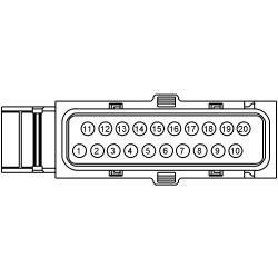
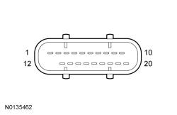
- Disconnect: Transmission Vehicle Harness C168 .
- Inspect the connector for damaged or pushed-out terminals, corrosion, loose wires and missing or damaged seals.
- Ignition ON.
- Enter the following diagnostic mode on the scan tool: TFT and TFTV PIDs.
Does the TFT PID display a temperature of -40 ° C (-40 ° F) and the TFTV PID display 4.9 volts?
Yes GO to S3. No REPAIR the circuit. - S3 CHECK THE TFT SENSOR SIGNAL CIRCUIT
- Connect a fused jumper wire
between.
Positive Lead Negative Lead Pin Circuit Pin Circuit C168-2 VET27 (BN/YE) C168-3 RE406 (GY/VT)
Does the TFT PID display a temperature of 191 °-198 °C (376 °-388 °F) and the TFTV PID display 0.0 to 0.2 volts?
Yes GO to S5. No GO to S4. - Connect a fused jumper wire
between.
- S4 CHECK THE TFT SENSOR SIGNAL VOLTAGE
- Measure the voltage
between.
Positive Lead Negative Lead Pin Circuit Pin Circuit C168-2 VET27 (BN/YE) - Ground
Is the voltage between 4.8 and 5.1 volts?
Yes GO to S5. No REPAIR the circuit. If an open circuit is not found, INSTALL a new PCM. REFER to Electronic Engine Controls . PERFORM the Solenoid Body Strategy Data Download procedure. REFER to Solenoid Body Strategy Download . - Measure the voltage
between.
- S5 CHECK THE TFT SENSOR RESISTANCE
- Measure the component side resistance
between.
Positive Lead Negative Lead Pin Circuit Pin Circuit 2 - 3 - Transmission Fluid Temperature
?C ?F Resistance (Ohms) -40 to -20 -40 to -4 1, 076K-269K -19 to -1 -3 to 31 309K-91K 0-20 32-68 104K-35K 21-40 69-104 40K-15K 41-70 105-158 17K-4.9K 71-90 159-194 5.6K-2.5K 91-110 195-230 3.0K-1.4K 111-130 231-266 1.7K-0.8K 131-150 267-302 0.97K-0.56K
Does the temperature to resistance specifications match?
Yes GO to Symptom Chart to diagnose an overheating concern. No INSTALL a new solenoid body assembly. REFER to Solenoid Body Assembly . PERFORM the Solenoid Body Strategy Data Download procedure. REFER to Solenoid Body Strategy Download . - Measure the component side resistance
between.
- S6 ON DEMAND SELF TEST
- Check and make sure the transmission vehicle harness C168 is fully seated, terminals are engaged in connector and in good condition before proceeding.
- Using the diagnostic scan tool, make sure the transmission fluid temperature is between 1.1 °C (30 °F) and 104 °C (220 °F).
- Perform the KOER self-test.
Did DTC P0711, P1711 and/or P1783 set?
Yes For DTCs P0711 and P1711, INSTALL a new solenoid body assembly. REFER to Solenoid Body Assembly . PERFORM the Solenoid Body Strategy Data Download procedure. REFER to Solenoid Body Strategy Download . For DTC P1783, REFER to Transaxle Transmission Cooling . No The system is operating correctly at this time. The concern may have been caused by a loose or corroded connector.