Transmission - Front Wheel Drive (FWD): Installation
NOTE:
Prior to installing a new, re-manufactured or overhauled transmission, the transmission fluid cooler tubes must be cleaned, otherwise transmission failure may occur.
NOTE:
Prior to installing a new, re-manufactured or overhauled transmission, flush out the cooler and cooler tubes. REFER to Transaxle Transmission Cooling
.
- 1.
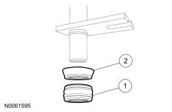
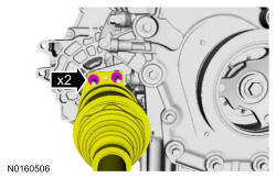
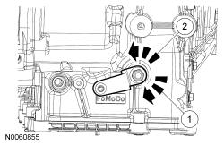
If removed, inspect the transmission mounted transmission fluid cooler tube backing rings and seals for damage and install new backing rings or seals if necessary. Lubricate the transmission mounted transmission fluid cooler tube seals with clean Motorcraft ®MERCON ® LV Automatic Transmission Fluid and install the backing rings and seals on the transmission mounted transmission fluid cooler tubes.Item Service Part Number Description 1 7D285 Seal 2 7J324 Backing ring
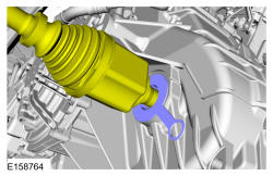
- 2.
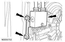
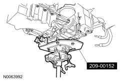
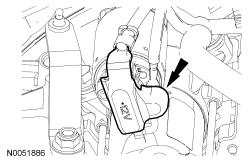
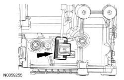
If removed, position the transmission fluid cooler thermal bypass valve and transmission mounted transmission fluid cooler tube assembly in place and install the nuts.- Tighten to 9 Nm (80 lb-in).
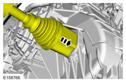
- 3.
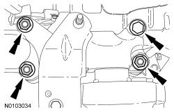
If removed, install new transmission mounted transmission fluid cooler tube bolts.- Tighten to 9 Nm (80 lb-in).
- 5.
If the dowel pins were pulled out of the engine block during removal, install new dowel pins in the engine block.
NOTE:
If the transmission is not positioned on the dowel pins, damage to the transmission may occur.
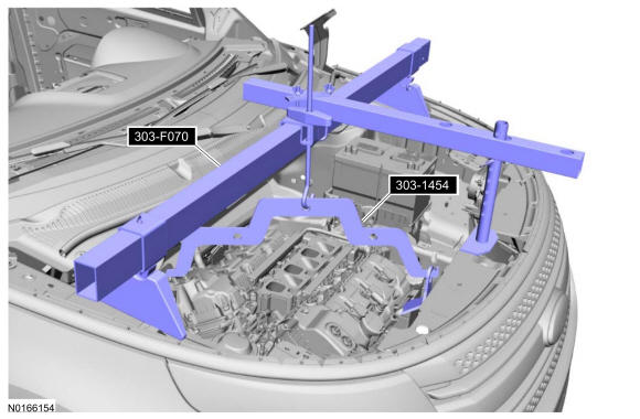
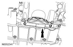
- 8.
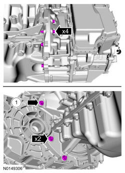
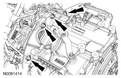
Position the transmission on the dowel pins and install the lower torque converter housing bolts.- 1.
If equipped.
- Tighten to 48 Nm (35 lb-ft).
- 1.
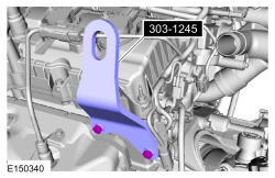
- 9.
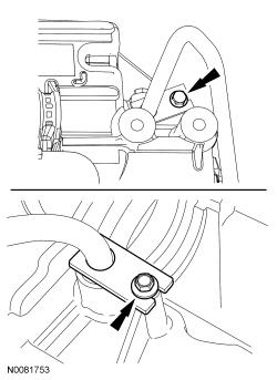
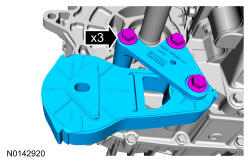
Install the transmission support insulator bracket, the nuts and the bolt.- Tighten the bolt to 80 Nm (59 lb-ft).
- Tighten the nuts to 63 Nm (46 lb-ft).
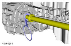
- 13.
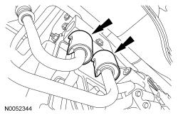
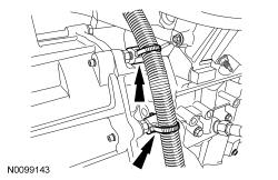
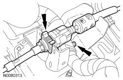
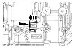
Install the transmission fluid cooler tubes in the transmission fluid cooler thermal bypass valve.
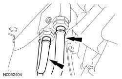
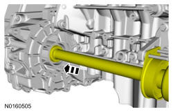
- 14.
Install the secondary latches on the transmission fluid cooler tubes at the transmission fluid cooler thermal bypass valve.
- 15.
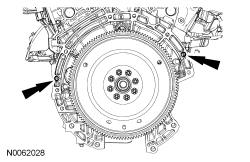
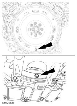
Install 3 new torque converter bolts (-W714722-).- Tighten to 55 Nm (41 lb-ft).
- Install the first torque converter bolt in the slotted hole on the flexplate.
NOTE:
Use only the specified bolts for the torque converter. Standard length fasteners may bottom out and damage the torque converter clutch apply surface.
- 17.
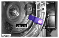
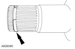
Install the correct new circlip on the inboard stub shaft.
NOTE:
The circlips are unique in size and shape for each shaft. Make sure to use the specified circlip for the application or vehicle damage may occur.
- 18.
Install a new LH halfshaft seal. REFER to, Halfshaft Seal - LH .
NOTE:
If the transmission has been replaced or overhauled, the halfshaft seals do not need to be replaced.
- 19.
Using part: AA5P-4N206-A.
NOTE:
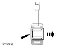
Remove the seal protector before the halfshaft is installed completely.
- 20.
NOTE:
Insert shaft until circlip is fully seated. When checking if circlip is seated do not pull on CV joint or damage can result.
NOTE:
After insertion, pull the halfshaft inner end to make sure the circlip is locked.
- 21.
Install a new RH halfshaft seal. REFER to, Halfshaft Seal - RH, Front Wheel Drive (FWD) .
- 22.
Using part: AA5P-4N206-A.
NOTE:
Remove the seal protector before the halfshaft is installed completely.
- 23.
NOTE:
Insert shaft until circlip is fully seated. When checking if circlip is seated do not pull on CV joint or damage can result.
NOTE:
After insertion, pull the halfshaft inner end to make sure the circlip is locked.
- 26.
Install the front subframe. REFER to Uni-Body, Subframe and Mounting System .
- 28.
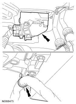
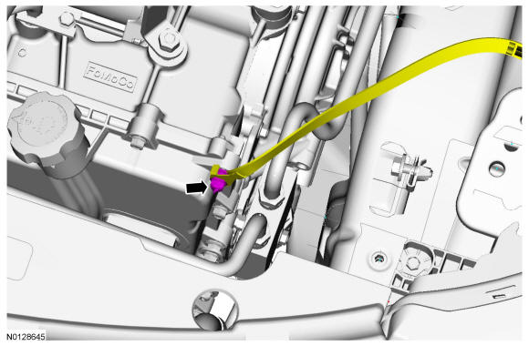
Connect the transmission electrical connector and install the wiring harness retainer on the main control cover stud bolt.
- 30.
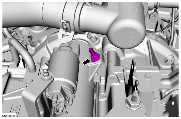
Install the ground strap and nut on the main control cover stud bolt.- Tighten to 11 Nm (97 lb-in).
- 32.
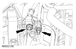
Attach the starter wire terminals and install the 2 nuts.- Tighten the B+ terminal nut to 12 Nm (106 lb-in).
- Tighten the S- terminal nut to 5 Nm (44 lb-in).
- 34.
Attach the wiring harness pin-type retainer and connect the selector lever cable to the selector lever cable bracket.
- 36.
Place the manual control lever in DRIVE.- 1.
Rotate the manual control lever clockwise until it stops.
- 2.
Rotate the manual control lever counterclockwise one detent.
- 1.
- 39.
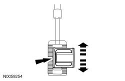
With the adjuster locking tab released, connect the selector lever cable end to the manual control lever.
- 41.
Install the upper intake manifold. For 3.5L Ti-VCT refer to ENGINE - 3.5L GTDI .
- 42.
Install the battery tray. REFER to Battery, Mounting and Cables .
- 43.
Install the ACL assembly. REFER to Intake Air Distribution and Filtering .
- 44.
Fill with clean Motorcraft ®MERCON ® LV Automatic Transmission Fluid to the correct level. Refer to Transmission Fluid Drain and Refill .
- 46.
If a replacement transmission assembly is being installed or a new solenoid body is installed, the solenoid body strategy will need to be updated. Refer to Solenoid Body Strategy Download .