Pinpoint Test C : Shift Solenoid C
WARNING: This page is about a different variant/trim than selected.
- C1 RETRIEVE AND RECORD ALL DTCS
- Using the diagnostic scan tool, retrieve all DTCs.
Are DTCs P0760, P0763, P0764, P0979 and/or P0980 present?
Yes For DTCs P0760, P0763, and P0764, GO to C2. For DTC P0979, GO to C5. For DTC P0980, GO to C7. No GO to Symptom Chart . - C2 CHECK THE SSC CIRCUIT FOR AN OPEN
- Ignition OFF.
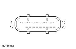
- Disconnect: Transmission Vehicle Harness C1520A .
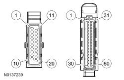
- Disconnect: TCM C1750 .
- Inspect the connectors for damaged or pushed-out terminals, corrosion, loose wires and missing or damaged seals.
- Measure the resistance
between.
Positive Lead Negative Lead Pin Circuit Pin Circuit C1520A-4 CET07 (GY/OG) C1750-6 CET07 (GY/OG)
Is the resistance less than 3 ohms?
Yes GO to C3. No REPAIR the circuit. - C3 CHECK THE SSC FOR AN OPEN
- Measure the component side resistance
between.
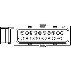
Positive Lead Negative Lead Pin Circuit Pin Circuit 4 - 5 -
Is the resistance between 4.0 and 7.2 ohms?
Yes INSTALL a new TCM. REFER to Transmission Control Module (TCM) . PROGRAM the TCM with the latest calibration level. PERFORM the Solenoid Body Strategy Download procedure. REFER to Solenoid Body Strategy Download . No GO to C4. - Measure the component side resistance
between.
- C4 CHECK THE SSC RESISTANCE
- Remove the solenoid body leadframe, refer to Solenoid Body Leadframe . Inspect for metal shavings on the exposed metal contacts or other components and clean the solenoid and solenoid body leadframe terminals.
Is the resistance between 4.0 and 7.2 ohms?
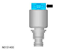
Yes INSTALL a new solenoid body leadframe. REFER to Solenoid Body Leadframe . No INSTALL a new SSC. REFER to Solenoids . - C5 CHECK THE SSC CIRCUIT FOR A SHORT TO GROUND
- Ignition OFF.
- Disconnect: Transmission Vehicle Harness C1520A .
- Disconnect: TCM C1750 .
- Inspect the connectors for damaged or pushed-out terminals, corrosion, loose wires and missing or damaged seals.
- Measure the resistance
between.
Positive Lead Negative Lead Pin Circuit Pin Circuit C1520A-4 CET07 (GY/OG) - Ground
Is the resistance greater than 10, 000 ohms?
Yes GO to C6. No REPAIR the circuit. - C6 CHECK THE SSC FOR A SHORT TO GROUND
- Remove the solenoid body leadframe, refer to Solenoid Body Leadframe . Inspect for metal shavings on the exposed metal contacts or other components and clean the solenoid and solenoid body leadframe terminals.
Is the resistance less than 3 ohms?
Yes INSTALL a new SSC. REFER to Solenoids . No INSTALL a new solenoid body leadframe. REFER to Solenoid Body Leadframe . - C7 CHECK THE SSC CIRCUIT FOR A SHORT TO VOLTAGE
- Ignition OFF.
- Disconnect: Transmission Vehicle Harness C1520A .
- Disconnect: TCM C1750 .
- Inspect the connectors for damaged or pushed-out terminals, corrosion, loose wires and missing or damaged seals.
- Ignition ON.
- Measure the voltage
between.
Positive Lead Negative Lead Pin Circuit Pin Circuit C1520A-4 CET07 (GY/OG) - Ground
Is any voltage present?
Yes REPAIR the circuit. No INSTALL a new TCM. REFER to Transmission Control Module (TCM) . PROGRAM the TCM with the latest calibration level. PERFORM the Solenoid Body Strategy Download procedure. REFER to Solenoid Body Strategy Download .