Pinpoint Test J : Transmission Range Sensor
WARNING: This page is about a different variant/trim than selected.
- J1 RETRIEVE AND RECORD ALL DTCS
- Using the diagnostic scan tool, retrieve all DTCs.
Are DTCs P0706, P0707, P0708, P0709, P1702, P1705 and/or P1921 present?
Yes For DTCs P0706, P0707, P0708, P0709, P1702 and/or P1921, GO to J2. For DTC P1705, GO to J9. No GO to Symptom Chart . - J2 VERIFY SELECTOR LEVER CABLE/LINKAGE ADJUSTMENT
- Verify the selector lever cable/linkage is correctly adjusted. For console shift, REFER to Automatic Transaxle Transmission External Controls Transmission Control Switch (TCS) or REFER to Automatic Transaxle Transmission External Controls Select Shift . For column shift, REFER to Automatic Transaxle-Transmission External Controls Column Shift .
Is the selector lever cable/linkage correctly adjusted?
Yes GO to J3. No CORRECT the selector lever cable/linkage adjustment. For console shift, REFER to Automatic Transaxle Transmission External Controls Transmission Control Switch (TCS) or REFER to Automatic Transaxle Transmission External Controls Select Shift . For column shift, REFER to Automatic Transaxle-Transmission External Controls Column Shift . REPEAT the self-test. If the TR sensor DTCs return, GO to J3. - J3 CHECK THE TR SENSOR CIRCUITS FOR AN OPEN
- Ignition OFF.
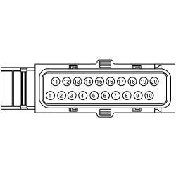
- Disconnect: Transmission Vehicle Harness C1520A .
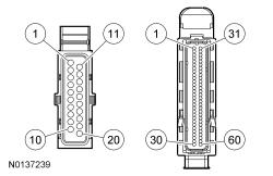
- Disconnect: TCM C1750 .
- Inspect the connectors for damaged or pushed-out terminals, corrosion, loose wires and missing or damaged seals.
- Measure the resistance
between.
Positive Lead Negative Lead Pin Circuit Pin Circuit C1520A-17 VET32 (VT) C1750-45 VET32 (VT) C1520A-18 LE111(VT/GN) C1750-20 LE111(VT/GN) C1520A-20 RET24 (BN/BU) C1750-49 RET24 (BN/BU)
Is the resistance less than 3 ohms?
Yes GO to J4. No REPAIR the circuit. - J4 CHECK THE TR SENSOR CIRCUITS FOR A SHORT TO GROUND
- Disconnect: Transmission Vehicle Harness C1520B .
- Measure the resistance
between.
Positive Lead Negative Lead Pin Circuit Pin Circuit C1520A-17 VET32 (VT) - Ground C1520A-18 LE111(VT/GN) - Ground C1520A-20 RET24 (BN/BU) - Ground
Are all resistances greater than 10, 000 ohms?
Yes GO to J5. No REPAIR the circuit. - J5 CHECK THE TR SENSOR CIRCUITS FOR A SHORT TO VOLTAGE
- Ignition ON.
- Measure the voltage
between.
Positive Lead Negative Lead Pin Circuit Pin Circuit C1520A-17 VET32 (VT) - Ground C1520A-18 LE111(VT/GN) - Ground C1520A-20 RET24 (BN/BU) - Ground
Is any voltage present?
Yes REPAIR the circuit. No GO to J6. - J6 CHECK THE TR SENSOR CIRCUITS SHORTED TOGETHER.
- Ignition OFF.
- Measure the resistance
between.
Positive Lead Negative Lead Pin Circuit Pin Circuit C1520A-20 RET24 (BN/BU) C1520A-18 LE111(VT/GN) C1520A-20 RET24 (BN/BU) C1520A-17 VET32 (VT) C1520A-18 LE111(VT/GN) C1520A-17 VET32 (VT)
Are all the resistances greater than 10, 000 ohms?
Yes GO to J7. No REPAIR the circuits. - J7 CHECK THE TR SENSOR CIRCUITS IN THE SOLENOID BODY LEADFRAME FOR AN OPEN
- Remove the main control cover. REFER to Main Control Cover .
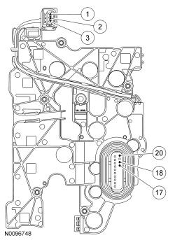
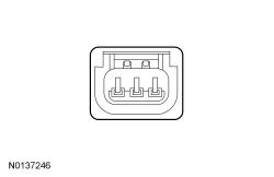
- Disconnect: TR Sensor.
- Inspect the connector for damaged or pushed-out terminals, corrosion, loose wires and missing or damaged seals.
- Measure the component side resistance
between.
Positive Lead Negative Lead Pin Circuit Pin Circuit 18 TR sensor voltage supply 1 TR sensor voltage supply 17 TR sensor signal 2 TR sensor signal 20 TR sensor ground 3 TR sensor ground
Is the resistance less than 3 ohms?
Yes GO to J8. No INSTALL a new solenoid body leadframe. REFER to Solenoid Body Leadframe . - J8 CHECK FOR VOLTAGE AND GROUND AT THE TR SENSOR
- Connect: TCM.
- Connect: C1520A .
- Connect: C1520B .
- Ignition ON.
- Measure the component side voltage
between.
Positive Lead Negative Lead Pin Circuit Pin Circuit 1 TR sensor voltage supply 3 TR sensor ground
Is the voltage greater than 10 volts?
Yes INSTALL a new TR sensor. REFER to Transmission Range (TR) Sensor . No CHECK OASIS for any applicable TSBs. If a TSB exists for this concern, discontinue this test and follow TSB instructions. If no TSBs address this concern, INSTALL a new TCM. REFER to Transmission Control Module (TCM) . PROGRAM the TCM with the latest calibration level. PERFORM the Solenoid Body Strategy Download procedure. REFER to Solenoid Body Strategy Download . - J9 ON DEMAND SELF-TEST
- Check to make sure the transmission harness connector is fully seated, the terminals are engaged in the connector and in good condition before proceeding.
- Using the diagnostic scan tool, make sure the selector lever is in the PARK or NEUTRAL position.
- Perform the KOEO self-test.
Did DTC P1705 return?
Yes VERIFY selector lever cable adjustment. For console shift, REFER to Automatic Transaxle Transmission External Controls Transmission Control Switch (TCS) or REFER to Automatic Transaxle Transmission External Controls Select Shift . For column shift, REFER to Automatic Transaxle-Transmission External Controls Column Shift . No The system is operating correctly at this time. The concern may have been caused by a loose or corroded connector. ADDRESS the root cause of any connector or terminal issues.