Pinpoint Test L : Output Shaft Speed Sensor
WARNING: This page is about a different variant/trim than selected.
- L1 RETRIEVE AND RECORD ALL DTCS
- Using the diagnostic scan tool, retrieve all DTCs.
Are DTCs P0720, P0721, P0722 and/or P0715 present?
Yes For DTCs P0720, P0721 and P0722, GO to L2. For DTC P0715 and P0720, GO to L6. No GO to Symptom Chart . - L2 CHECK OSS SENSOR SIGNAL CIRCUIT FOR AN OPEN
- Ignition OFF.
- Disconnect: Transmission Vehicle Harness C1520A .
- Disconnect: TCM C1750 .
- Inspect the connectors for damaged or pushed-out terminals, corrosion, loose wires and missing or damaged seals.
- Measure the resistance
between.
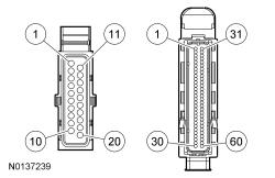
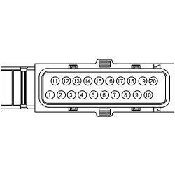
Positive Lead Negative Lead Pin Circuit Pin Circuit C1520A-19 VET26 (BN/GN) C1750-51 VET26 (BN/GN)
Is the resistance less than 3 ohms?
Yes GO to L3. No REPAIR the circuit. - L3 CHECK OSS SENSOR SIGNAL CIRCUIT FOR A SHORT TO GROUND
- Measure the resistance
between.
Positive Lead Negative Lead Pin Circuit Pin Circuit C1520A-19 VET26 (BN/GN) - Ground
Is the resistance greater than 10, 000 ohms?
Yes GO to L4. No REPAIR the circuit. - Measure the resistance
between.
- L4 CHECK OSS SENSOR SIGNAL CIRCUIT FOR A SHORT TO POWER
- Ignition ON.
- Measure the voltage
between.
Positive Lead Negative Lead Pin Circuit Pin Circuit C1520A-19 VET26 (BN/GN) - Ground
Is any voltage present?
Yes REPAIR the circuit. No GO to L5. - L5 CHECK THE OSS SENSOR GROUND CIRCUIT
- Ignition OFF.
- Connect: TCM C1750 .
- Ignition ON.
- Measure the voltage
between.
Positive Lead Negative Lead Pin Circuit Pin Circuit C1520A-18 LE111 (VT/GN) C1520A-20 RET24 (BN/BU)
Is voltage less than 4.8 volts?
Yes INSPECT and REPAIR the circuit. If an open circuit is not found, INSTALL a new TCM. REFER to Transmission Control Module (TCM) . PROGRAM the TCM with the latest calibration level. PERFORM the Solenoid Body Strategy Download procedure. REFER to Solenoid Body Strategy Download . No INSTALL a new OSS sensor. REFER to Output Shaft Speed (OSS) Sensor . - L6 CHECK OSS SENSOR VPWR CIRCUIT FOR AN OPEN
- Ignition OFF.
- Disconnect: Transmission Vehicle Harness C1520A .
- Inspect the connectors for damaged or pushed-out terminals, corrosion, loose wires and missing or damaged seals.
- Ignition ON.
- Measure the voltage
between.
Positive Lead Negative Lead Pin Circuit Pin Circuit C1520A-18 LE111 (VT/GN) - Ground
Is the voltage less than 9.5 volts?
Yes INSPECT and REPAIR the circuit. If an open circuit is not found, INSTALL a new TCM. REFER to Transmission Control Module (TCM) . PROGRAM the TCM with the latest calibration level. PERFORM the Solenoid Body Strategy Download procedure. REFER to Solenoid Body Strategy Download . No ROAD TEST the vehicle, if DTCs P0715 and/or P0720 return, INSTALL a new TCM. REFER to Transmission Control Module (TCM) . PROGRAM the TCM with the latest calibration level. PERFORM the Solenoid Body Strategy Download procedure. REFER to Solenoid Body Strategy Download .