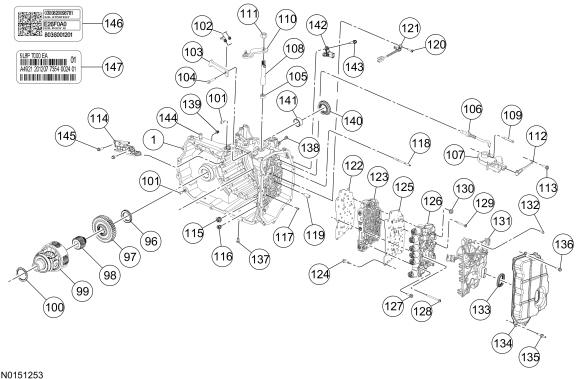
Disassembled Views
WARNING: This page is about a different variant/trim than selected.
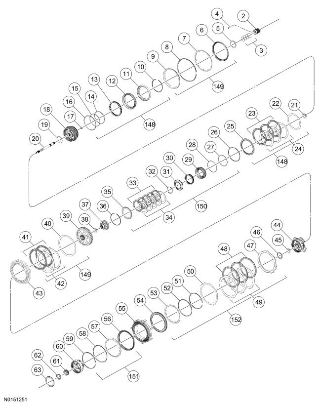
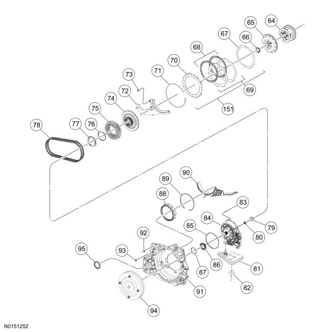
| Item | Part Number | Description |
|---|---|---|
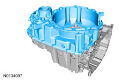
| 1 | 7005 | Transmission case |
| 2 | 7A130 | Clutch support tower |
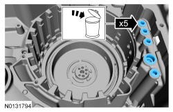
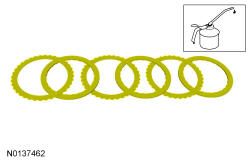
| 3 | 7D019 | Clutch support tower seals (4 required) |
| 4 | W302855 | Clutch support tower bolt (3 required) |
| 5 | 7F242 | No. 1 thrust bearing |
| 6 | 7E005 | Intermediate (2, 6) clutch piston |
| 7 | 7B070 | Intermediate (2, 6) clutch piston return spring |
| 8 | 7D483 | Intermediate (2, 6) clutch return spring snap ring |
| 9 | 7E005 | Intermediate (2, 6) clutch apply ring |
| 10 | 7C122 | Direct (3, 5, R) clutch cylinder snap ring |
| 11 | 7F283 | Direct (3, 5, R) clutch cylinder |
| 12 | 7A262 | Direct (3, 5, R) clutch piston |
| 13 | 7F235 | Direct (3, 5, R) clutch piston return spring |
| 14 | 7C099 | Direct (3, 5, R) clutch piston inner (rear) seal |
| 15 | 7C099 | Direct (3, 5, R) clutch piston inner (front) seal |
| 16 | 7A548 | Direct (3, 5, R) clutch piston outer seal |
| 17 | 7C122 | Input shaft snap ring |
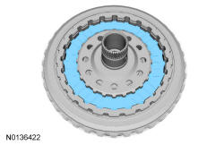
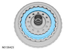
| 18 | 7G384 | Direct (3, 5, R)/overdrive (4, 5, 6) clutch cylinder and hub assembly |
| 19 | 7A548 | Overdrive (4, 5, 6) clutch piston inner seal |
| 20 | 7F213 | Input shaft |
| 21 | 7D234 | No. 2 thrust bearing |
| 22 | 7B070 | Direct (3, 5, R) clutch wave spring |
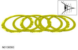
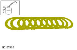
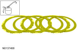
| 23 | 7B164 | Direct (3, 5, R) clutch friction plates (3 required) |
| 24 | 7B442 | Direct (3, 5, R) clutch steel plates (3 required) |
| 25 | 7B066 | Direct (3, 5, R) clutch pressure plate |
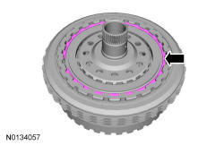
| 26 | 7D483 | Direct (3, 5, R) clutch snap ring |
| 27 | 7A548 | Overdrive (4, 5, 6) clutch piston outer (rear) seal |
| 28 | 7A548 | Overdrive (4, 5, 6) clutch piston outer (front) seal |
| 29 | 7A262 | Overdrive (4, 5, 6) clutch piston |
| 30 | 7F222 | Overdrive (4, 5, 6) clutch piston return spring |
| 31 | 7H360 | Overdrive (4, 5, 6) clutch balance piston |
| 32 | 7C122 | Overdrive (4, 5, 6) clutch piston snap ring |
| 33 | 7B164 7B16 | Overdrive (4, 5, 6) clutch friction plates (5 required) |
| 34 | 7B442 | Overdrive (4, 5, 6) clutch steel plates (5 required) |
| 35 | 7B066 | Overdrive (4, 5, 6) clutch pressure plate |
| 36 | 7D483 | Overdrive (4, 5, 6) clutch snap ring |
| 37 | 7H351 | Overdrive (4, 5, 6) clutch hub |
| 38 | 7D234 | No. 3 thrust bearing |
| 39 | 7A019 | Rear planetary sun gear and shell assembly |
| 40 | 7E085 | Intermediate (2, 6) clutch wave spring |
| 41 | 7B164 | Intermediate (2, 6) clutch friction plates (2 required) |
| 42 | 7B442 | Intermediate (2, 6) clutch steel plates (2 required) |
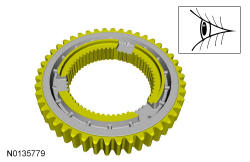
| 43 | 7A089 | OWC |
| 44 | 7D491 | Rear planet carrier/center ring gear |
| 45 | 7C096 | No. 6 thrust bearing |
| 46 | 7G177 | No. 5 thrust bearing |
| 47 | 7B066 | Low/reverse clutch pressure plate |
| 48 | 7B164 | Low/reverse clutch friction plates (3 required) |
| 49 | 7B442 | Low/reverse clutch steel plates (3 required) |
| 50 | 7E085 | Low/reverse clutch wave spring |
| 51 | 7C122 | Low/reverse clutch piston snap ring |
| 52 | 7H318 | Low/reverse clutch piston snap ring retainer |
| 53 | 7B070 | Low/reverse clutch piston return spring |
| 54 | 7D402 | Low/reverse clutch piston |
| 55 | 7L328 | Center support |
| 56 | 7A262 | Forward (1, 2, 3, 4) clutch piston |
| 57 | 7B070 | Forward (1, 2, 3, 4) clutch piston return spring |
| 58 | 7D041 7D04 | Forward (1, 2, 3, 4) clutch piston snap ring retainer |
| 59 | 7H365 | Forward (1, 2, 3, 4) clutch piston snap ring |
| 60 | 7D491 | Center planetary carrier/front ring gear |
| 61 | 7D063 | Center planetary sun gear |
| 62 | 7C096 | No. 7 thrust bearing |
| 63 | 7C096 | No. 8 thrust bearing |
| 64 | 7D491 | Front planetary carrier/rear ring gear |
| 65 | 7A019 | Front planetary sun gear and shell assembly |
| 66 | 7D234 | No. 10 thrust bearing |
| 67 | 7B070 | Forward (1, 2, 3, 4) clutch wave spring |
| 68 | 7B164 | Forward (1, 2, 3, 4) clutch friction plates (2 required) |
| 69 | 7B442 | Forward (1, 2, 3, 4) clutch steel plates (2 required) |
| 70 | 7B066 | Forward (1, 2, 3, 4) clutch pressure plate |
| 71 | 7D483 | Forward (1, 2, 3, 4) clutch snap ring |
| 72 | 7978 | Transmission fluid baffle |
| 73 | W500214 | Transmission fluid baffle bolt (2 required) |
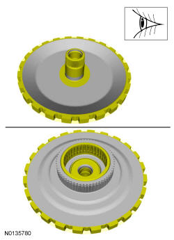
| 74 | 7060 | Park gear |
| 75 | 7G132 | Drive chain drive sprocket |
| 76 | 7C122 | Drive sprocket snap ring |
| 77 | 7G099 | No. 13 thrust washer |
| 78 | 7G249 | Drive chain |
| 79 | 7D234 | No. 11 thrust bearing |
| 80 | 7048 | Input shaft seal |
| 81 | 7A098 | Transmission fluid filter |
| 82 | 7L027 | Magnet |
| 83 | W302860 | Pump-to-torque converter housing bolt (8 required) |
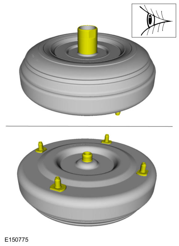
| 84 | 7A103 | Pump assembly |
| 85 | 7A248 | Pump assembly-to-torque converter housing O-ring seal |
| 86 | 7A248 | Torque converter hub seal |
| 87 | 7P113 | Torque converter hub seal retainer |
| 88 | 7F343 | Different ring gear |
| 89 | 7C122 | Differential ring gear snap ring |
| 90 | 7H245 | Differential transmission fluid baffle |
| 91 | 7975 | Torque converter housing |
| 92 | W701606 | Torque converter housing stud bolt |
| 93 | 7A443 | Torque converter housing bolt (16 required) |
| 94 | 7902 | Torque converter |
| 95 | 1177 | RH halfshaft seal |
| 96 | 7G355 | No. 12 thrust bearing |
| 97 | 7G132 | Drive chain driven sprocket |
| 98 | 7F342 | Differential sun gear |
| 99 | 7F465 | Differential assembly |
| 100 | 7G112 | No. 15 thrust bearing |
| 101 | 7B362 | Torque converter housing-to-transmission case guide pins |
| 102 | 7D070 | Park pawl spring |
| 103 | 7A441 | Park pawl |
| 104 | 7D071 | Park pawl pin |
| 105 | 7F337 | Manual control shaft seal |
| 106 | 7A232 | Park pawl actuator rod |
| 107 | 7H557 | TR sensor |
| 108 | 7C493 | Manual control shaft |
| 109 | 7G100 | Manual control shaft pin |
| 110 | 7A256 | Manual control lever |
| 111 | W708455 | Manual control lever nut |
| 112 | 7E332 | Manual valve detent spring |
| 113 | W711235 | TR sensor detent spring bolt |
| 114 | 7J387 | Fluid reservoir |
| 115 | 7A248 | Clutch feed seal (large) |
| 116 | 7A248 | Clutch feed seal (small) (4 required) |
| 117 | 7B431 | Main control alignment pin |
| 118 | 7C207 | Main control stud |
| 119 | 7G199 | Main control-to-transmission case seal (2 required) |
| 120 | W713644 | OSS sensor bolt |
| 121 | 7H103 | OSS sensor |
| 122 | 7Z490 | Main control-to-transmission case separator plate |
| 123 | 7A100 | Main control valve body |
| 124 | N605770 | Separator plate-to-solenoid body bolt (2 required) |
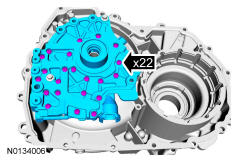
| 125 | 7Z490 | Main control valve body-to-solenoid body separator plate |
| 126 | 7G391 | Solenoid body |
| 127 | W500303 | Solenoid body-to-valve body bolt (2 required) |
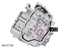
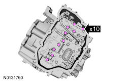
| 128 | W302863 | Main control-to-transmission case bolt (long) (10 required) |
| 129 | W302862 | Main control-to-transmission case bolt (short) (12 required) |
| 130 | W520412 | Main control nut |
| 131 | 7G276 | Main control leadframe |
| 132 | W505513 | Main control leadframe screw (5 required) |
| 133 | 7B329 | Main control-to-cover seal |
| 134 | 7G004 | Main control cover |
| 135 | W714629 | Main control cover stud bolt (5 required) |
| 136 | W500214 | Main control cover bolt (8 required) |
| 137 | 7010 | Drain plug |
| 138 | 7H398 | Line pressure tap |
| 139 | - | Oil leveling plug |
| 140 | 1177 | LH halfshaft seal |
| 141 | 7025 | LH halfshaft bushing |
| 142 | 7M101 | TSS sensor |
| 143 | W500214 | TSS sensor bolt |
| 144 | 7A246 | Vent tube |
| 145 | W500214 | Fluid reservoir bolts |
| 146 | 7G342 | Solenoid body strategy tag |
| 147 | 7B148 | Transmission service identification tag |
| 148 | - | Direct clutch (3, 5, R) |
| 149 | - | Intermediate clutch (2, 6) |
| 150 | - | Overdrive clutch (4, 5, 6) |
| 151 | - | Forward clutch (1, 2, 3, 4) |
| 152 | - | Low/reverse clutch |
All vehicles
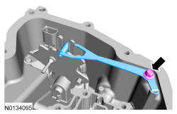
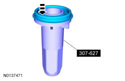
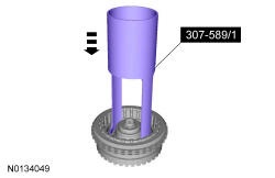
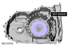
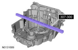
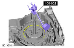
- 1.
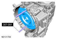
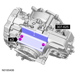
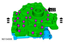
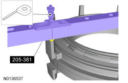
Install the special tool.
NOTE:
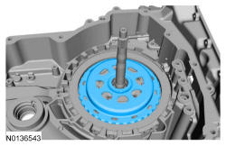
Use M10 x 1.5 x 25mm bolts to attach the special tool to the transmission case.
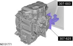

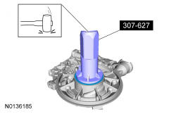
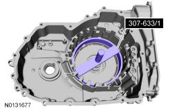
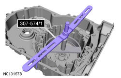
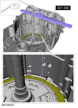
- 4.
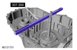
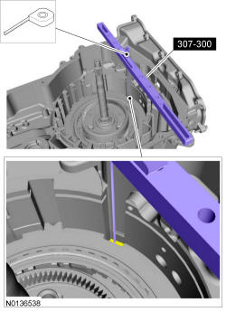
Using the special tools, remove the torque converter from the transmission.
NOTE:
The torque converter is heavy. Be careful not to drop it or damage will result.
- 5.
A new or remanufactured torque converter must be installed if one or more of the following statements is true:- The sealing surface has a groove worn from the seal.
- A torque converter malfunction has been determined based on complete diagnostic procedures.
- The torque converter stud or studs, threaded pads, impeller hub or bushing are damaged.
- The torque converter exhibits external discoloration (due to overheating).
- There is evidence of water or antifreeze contamination.
Flush The Torque Converter With The Transmission Cooling System Heated Flusher
- 6.
The torque converter must be flushed every time the transmission is overhauled. It is mandatory that proper equipment and procedures be followed when flushing the torque converter. The flushing equipment used MUST:- Maintain the transmission fluid at 140 °F or above
- Pulsate the transmission fluid during cleaning
- Have a GPM flow meter
- Have a filter with a rating of 100 micron or less
- Have air purge capability before and after flushing
NOTE:
Use transmission fluid specified for this transmission. Do not use any supplemental transmission fluid additives or cleaning agents. The use of these products could cause internal transmission components to fail, which will affect the operation of the transmission.
- 7.
If equipment meeting the specifications above is not available, the torque converter must be flushed by hand. Go to Flush The Torque Converter By Hand steps later in this procedure.
- 8.
Check and top off the transmission fluid level of the transmission cooling system heated flusher with transmission fluid.
- 9.
Turn on the heater and allow the transmission fluid in the transmission cooling system heated flusher 15-30 minutes to heat up to 60 °C (140 °F) before using.
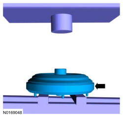
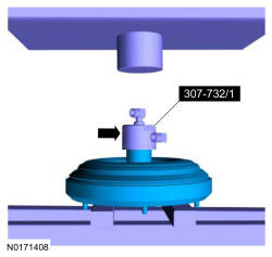
- 11.
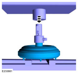
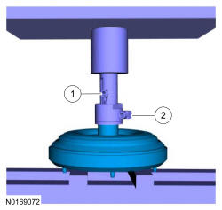
Using the special tools, assemble the correct turbine shaft simulator to the torque converter flush main hub and place it on the torque converter hub. Special Tool(s): Tool Kit, Torque Converter Flusher 307-732
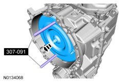
- 12.
Using the special tool, install the slotted cap. Special Tool(s): Tool Kit, Leak Tester, Torque Converter 307-691
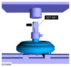
- 13.
Apply enough force from the press to seal the torque converter flush main hub to the torque converter hub.
- 15.
Follow the equipment instructions to purge the transmission fluid from the torque converter prior to starting the flushing procedure.
- 16.
Forward flush the converter for 15 minutes.
NOTE:
Maintain visual contact with torque converter during the entire flush procedure. Immediately stop the flush machine if a leak develops. Repeat set up steps to reseal the tool to the converter hub and continue flushing.
WARNING:
The torque converter, adaptor 307-732, and the hoses will be hot.
- 17.
Monitor GPM flow meter periodically during the flush procedure. Flow rate above 2.0 gallons per minute is required to break up and dislodge any contamination trapped behind the TCC (torque converter clutch) plate. Service flush machine filter(s) if flow rate drops below 2 GPM.
- 19.WARNING: The torque converter, adaptor 307-732, and the hoses will be hot.
Allow torque converter and equipment to cool for 30 minutes before handling.
Flush The Torque Converter By Hand
NOTE:
Do not use water-based cleaners or mineral spirits to clean or flush the torque converter or transmission damage will occur. Use only clean transmission fluid designated for the transmission and torque converter being serviced.
NOTE:
Only flush the torque converter by hand when the transmission cooling system heated flusher is not available.
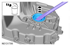
- 21.
Pour a small amount of transmission fluid from the torque converter onto an absorbent white tissue or through a paper filter.
- 22.
Examine the transmission fluid for contaminants. The transmission fluid must be free of metallic contaminants. If metallic contaminants are present, do not continue with hand flushing. The torque converter must be flushed with the transmission cooling system heated flusher.
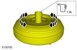
- 24.
Using only the recommended transmission fluid, add 1.9L (2 qt) of clean transmission fluid into the converter and agitate by hand.
All vehicles
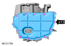
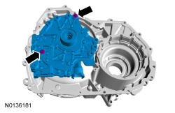
- 26.
Remove the main control cover bolts and the main control cover.
NOTE:
Note the location of the stud bolts for assembly.
- 30.
Remove the main control nut and the main control-to-transmission case bolts and remove the main control assembly.
NOTE:
Note the location of the short and long main control-to-transmission case bolts for reassembly.
NOTE:
If the transmission internal wiring harness frame has melted due to overheat condition the transmission and cooler must be replaced.
- 31.
Clean and inspect the main control assembly for damage. If damage is found install a new main control assembly. If the main control assembly is not damaged, disassemble the main control assembly and clean it. Refer to Main Control - Overhaul .
- 33.
Remove and discard the forward (1, 2, 3, 4) clutch and low/reverse clutch main control-to-transmission case seals.
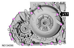
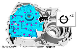
- 37.
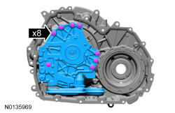
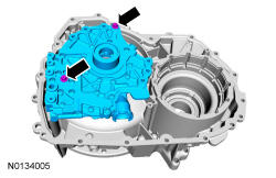
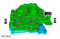
Remove the torque converter housing bolts.
NOTE:
Note the location of the stud bolts for assembly.
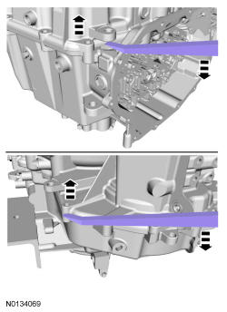
- 42.
Check that bearings spin freely and do not move back and forth or side to side excessively. Check for damage or excessive wear. Install new components, if necessary. Refer to Differential Gear Assembly .
- 45.
Remove the differential transmission fluid baffle.
NOTE:
If the transmission plastic baffle has melted due to overheat condition the transmission and cooler must be replaced.
- 49.
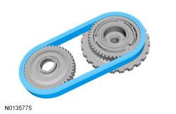
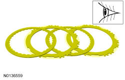
Clean and inspect the drive chain for damage or excessive wear and install new, if necessary.- Check for stretching or tightness of the chain links.
- Check that the chain moves freely.

- 50.
Inspect the driven sprocket for damage or excessive wear and install new, if necessary.- Chain teeth
- Spline teeth
- Thrust bearing surfaces
- Bearing
- 51.
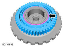
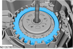
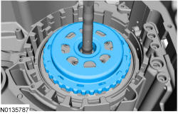
Remove the snap ring and remove the drive sprocket from the front planetary hub/park gear assembly.
- 52.
Inspect the drive sprocket for damage or excessive wear and install new, if necessary.- Chain teeth
- Spline teeth
- Thrust washer surface
- 53.
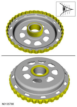
Inspect the front planetary hub/park gear assembly for damage or excessive wear and install new, if necessary.- Park gear teeth
- Spline teeth
- Thrust washer surface
- Thrust bearing surface
- Bearing surfaces
- Needle bearing
- 54.
Install the drive sprocket on the front planetary hub/park gear assembly and install the snap ring.
- 56.
- 1.
Remove the No. 12 driven sprocket thrust bearing.
- 2.
Remove the No. 10 front sun gear and shell assembly thrust bearing.
- 1.
- 61.
Remove the forward (1, 2, 3, 4) clutch snap ring.
NOTE:
The forward (1, 2, 3, 4) clutch snap ring gap faces the front of the transmission.
NOTE:
The forward (1, 2, 3, 4) clutch snap ring is beveled. The beveled side of the snap ring goes up (flat side down).
- 65.
Clean and inspect the front planetary sun gear and shell assembly for damage or wear and install new, as necessary.- Gear teeth
- Shell-to-clutch pack surfaces
- Thrust bearing surfaces
- 67.
Clean and inspect the front planetary carrier/rear ring gear assembly for damage or excessive wear and install new, as necessary.- Pinion gear teeth
- Pinion gear surfaces
- Pinion gear bearings
- Spline teeth
- Thrust bearing
- Thrust bearing surfaces
- Ring gear teeth
- 70.
Clean and inspect the center planetary carrier/front ring gear assembly for damage or excessive wear and install new, as necessary.- Pinion gear teeth
- Pinion gear surfaces
- Pinion gear bearings
- Spline teeth
- Thrust bearing surfaces
- Ring gear teeth
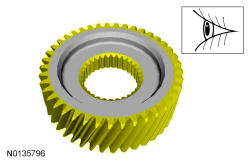
- 72.
Clean and inspect the center planetary sun gear for damage or excessive wear and install new, as necessary.- Sun gear teeth
- Spline teeth
- 76.
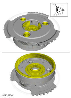
Clean and inspect the rear planetary carrier/center ring gear assembly for damage or excessive wear and install new, as necessary.- Pinion gear teeth
- Pinion gear surfaces
- Pinion gear bearings
- Spline teeth
- Thrust bearing surfaces
- Thrust bearing
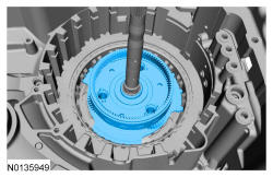
- 78.
Inspect the low/reverse clutch pack and pressure plate surface for damage or excessive wear and install new, if necessary.
- 80.
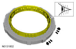
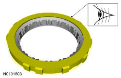
Clean and inspect the low OWC for cracks and damaged splines. The internal splined section should rotate clockwise and lock when rotated counterclockwise. If any damage is found or the clutch does not rotate or lock, install a new low OWC.
NOTE:
The low OWC should not be disassembled.
NOTE:
Do not clean in water or with water-based solvents. Damage to the component may occur.
- 81.
Inspect the intermediate (2, 6) clutch surface for damage. If the surface is burned or worn excessively, install a new low OWC.
- 82.
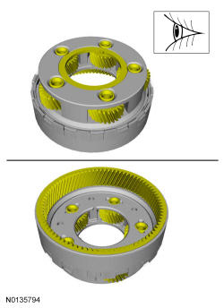
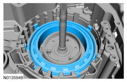
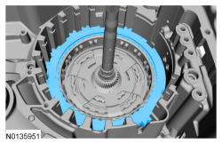
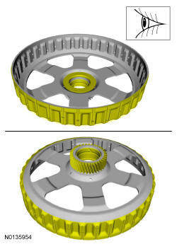
Remove the rear planetary sun gear and shell assembly and remove the intermediate (2, 6) clutch from the assembly.
NOTE:
The intermediate (2, 6) clutch is removed with the rear planetary sun gear and shell assembly.
- 83.
Inspect the intermediate (2, 6) clutch surface for damage or excessive wear and install new, if necessary.
- 84.
Clean and inspect the rear planetary sun gear and shell assembly for damage or wear and install new, if necessary.- Sun gear teeth
- Shell-to-clutch pack surfaces
- Bearing surfaces
- 89.
Remove the No. 1 thrust bearing.
NOTE:
If the No. 1 thrust bearing is stuck to the overdrive/direct clutch assembly, remove the No. 1 thrust bearing from the overdrive/direct clutch assembly.
- 92.
Remove the intermediate (2, 6) clutch return spring snap ring.
NOTE:
Note the location of the snap ring gap for assembly.
- 93.
Remove the intermediate (2, 6) clutch return spring.
NOTE:
Note the position of the return spring for assembly.
- 94.
Remove the intermediate (2, 6) clutch piston.
NOTE:
Note the position of the intermediate clutch piston for assembly.
- 97.
Using the special tool, pull the manual control shaft pin out of the manual control shaft.
NOTE:
Do not drive the manual control shaft pin through the manual control shaft. The manual control shaft pin will contact the transmission case causing damage to the transmission case.
- 99.
Remove the TR sensor and the park pawl actuator rod and remove the park pawl actuator rod from the TR sensor.
- 102.
- Clean and inspect the LH transmission case bushing and the bushing surface on the LH halfshaft for damage or excessive wear. If the LH transmission case bushing or the LH halfshaft shows signs of excessive wear or damage, install new components. Refer to Transmission Case .
NOTE: If the LH transmission case bushing or the LH halfshaft bushing surface shows signs of excessive wear or damage, a new LH transmission case bushing and a new LH halfshaft must be installed, or excessive noise or transmission failure can occur.- Make sure that the mating faces are clean and free of foreign material. Refer to RTV Sealing Surface Cleaning and Preparation in Engine System General Information .
NOTE: Do not use metal scrapers, wire brushes, power abrasive discs, or other abrasive means to clean sealing surfaces. These tools cause scratches and gouges which make leak paths.
- 105.
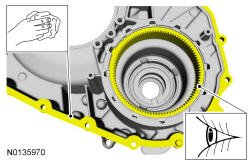
- Inspect the torque converter housing and the differential ring gear for damage or excessive wear. If the differential ring gear shows signs of excessive wear or damage replace the differential ring gear. Refer to Transmission Case .
- Make sure that the mating faces are clean and free of foreign material. Refer to RTV Sealing Surface Cleaning and Preparation in Engine System General Information .
NOTE: Do not use metal scrapers, wire brushes, power abrasive discs, or other abrasive means to clean sealing surfaces. These tools cause scratches and gouges which make leak paths.
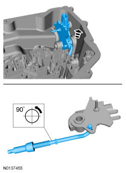
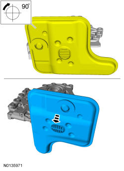
- 106.
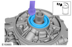
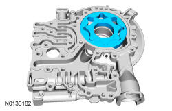
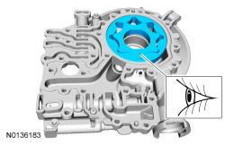
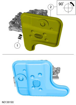
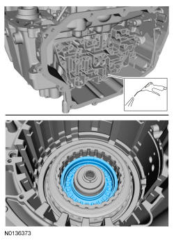
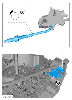
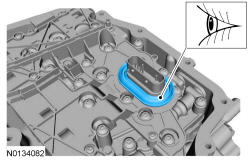
Rotate the transmission fluid filter 90 degrees clockwise and pull the transmission fluid filter out of the pump assembly.
NOTE:
Note the orientation of the transmission fluid filter to the fluid pump assembly.

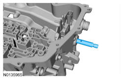
- 112.
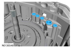
Position the pump assembly in the torque converter housing and install 2 pump-to-torque converter housing bolts hand-tight.
- 114.
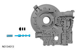
Remove the pump-to-torque converter housing bolts and the pump assembly from the torque converter housing.
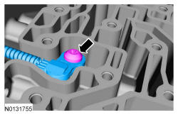
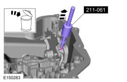
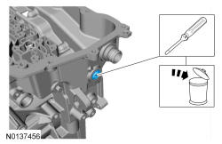
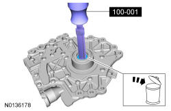
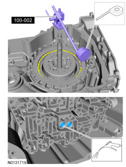
- 117.
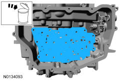
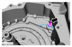
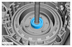
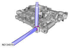
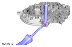
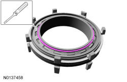
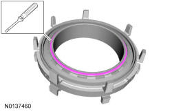
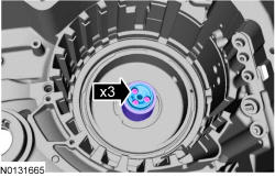
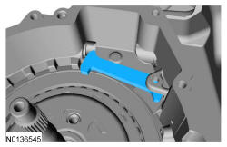
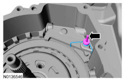
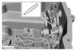
Compress the main pressure regulator valve spring with a screwdriver and remove the retainer with a magnet.
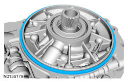
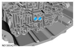
- 122.
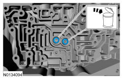
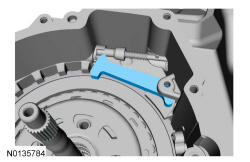
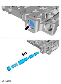
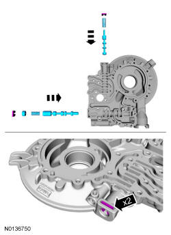
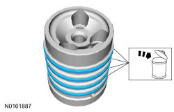
Assemble the TCC control valve assembly and main pressure regulator valve assembly and install the valves in the pump. Compress the valve springs with a screwdriver and install the retainers.
NOTE:
TCC control valve retainer shown assembled in the pump body, main pressure regulator valve retainer similar.
- 125.
Install the pump assembly in the torque converter housing and install 2 pump-to-torque converter housing bolts hand-tight.
- 127.
Remove the pump-to-torque converter housing bolts and the pump assembly from the torque converter housing.
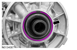
- 134.
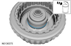
Install a new O-ring on a new transmission fluid filter and lubricate it with transmission fluid.
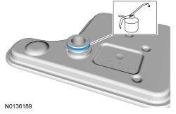
- 136.
Install the transmission fluid filter.- 1.
Position the transmission fluid filter in the pump assembly.
- 2.
Rotate the transmission fluid filter counterclockwise 90 degrees.
- 1.
- 137.
Using the special tool and a press, compress the low/reverse clutch return spring and remove the snap ring and the snap ring retainer.
NOTE:
The low/reverse clutch piston in the center support is the side of the center support with the long legs.
NOTE:
The piston return spring, snap ring or snap ring retainer from the low/reverse clutch side of the center support are not interchangeable with the forward clutch side of the center support. When disassembling the center support, be careful not to mix the components from the low/reverse clutch side with the forward clutch side of the center support. Failure to assemble the center support with the components in the correct side will result in damage to the center support, low/ reverse or forward clutch.
- 139.
Apply 483 kPa (70 psi) of air pressure to the low/reverse clutch piston port and remove the low/reverse clutch piston.
- 140.
Using the special tool and a press, compress the forward (1, 2, 3, 4) clutch return spring and remove the snap ring and the snap ring retainer.
NOTE:
The forward clutch piston in the center support is the side of the center support with the short legs.
- 142.
Apply 483 kPa (70 psi) of air pressure to the forward (1, 2, 3, 4) clutch piston port and remove the forward (1, 2, 3, 4) clutch piston.
- 144.
Install the special tools on the forward clutch piston side of the center support.
NOTE:
The forward clutch piston in the center support is the side of the center support with the short legs.
- 146.
Position the forward (1, 2, 3, 4) clutch piston on the special tools and push it down into the center support.
- 147.
Install the forward (1, 2, 3, 4) clutch piston return spring.
NOTE:
The piston return spring, snap ring or snap ring retainer from the low/reverse clutch side of the center support are not interchangeable with the forward clutch side of the center support. When assembling the center support, be careful not to mix the components from the low/reverse clutch side with the forward clutch side of the center support. Failure to assemble the center support with the components in the correct side will result in damage to the center support, low/reverse or forward clutch.
- 148.
Using the special tools and a press, compress the forward (1, 2, 3, 4) clutch return spring and install the snap ring retainer and the snap ring.
- 150.
Turn the center support over and install the special tools on the low/reverse piston side of the center support.
- 152.
Position the low/reverse clutch piston on the special tools and push it down into the center support.
- 154.
Using the special tools and a press, compress the low/reverse clutch return spring and install the snap ring retainer and the snap ring.
- 157.
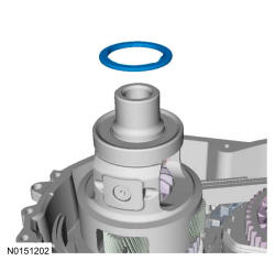
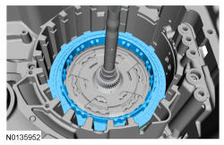
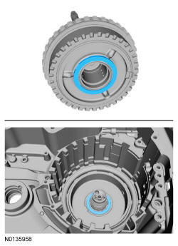
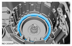
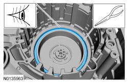
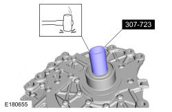
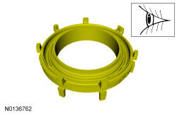
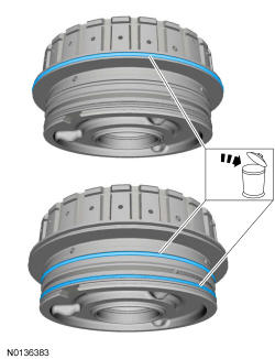
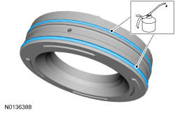
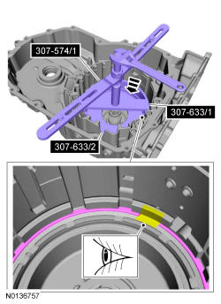
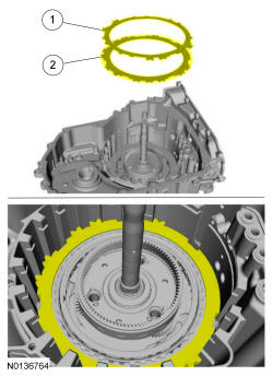
Clean and inspect the clutch support tower for damage. Install a new clutch support tower if damaged.
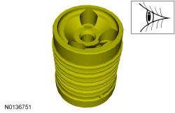
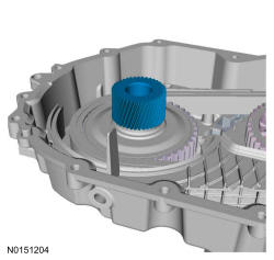
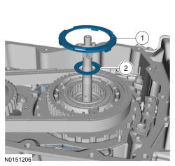
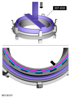
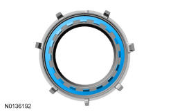
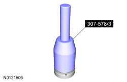
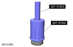
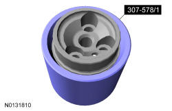
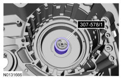
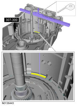
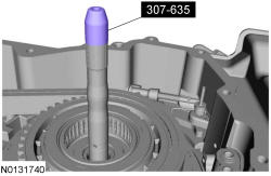
- 158.
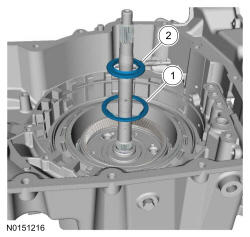
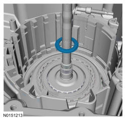
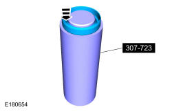
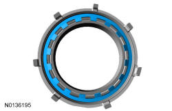
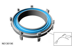
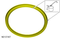
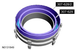
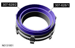
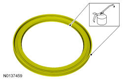
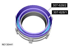
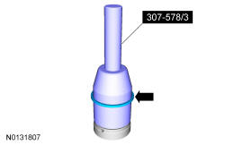
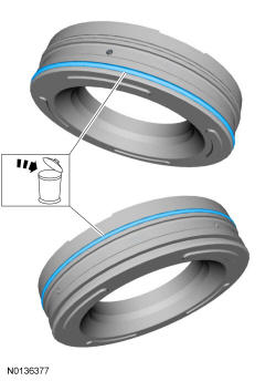
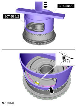
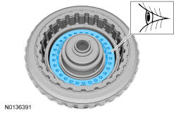
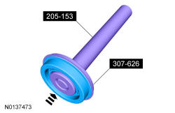
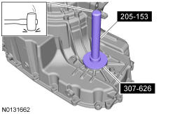
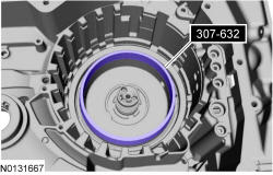
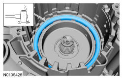
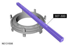
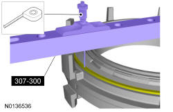
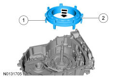
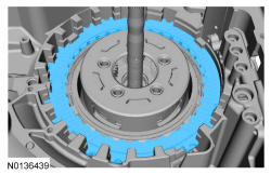
Install the special tool on the clutch support tower and adjust the special tool to align the bottom edge of the tool with the top edge of the bottom Teflon ® seal groove.
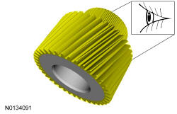
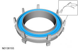
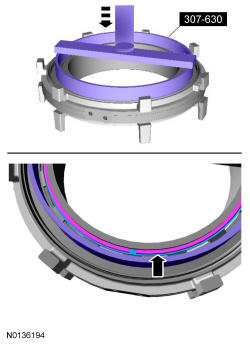
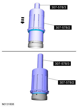
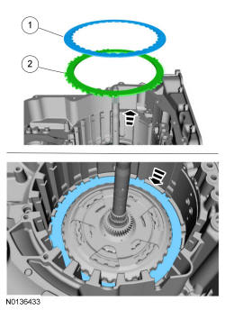
- 160.
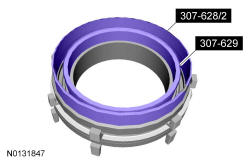
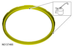
Install the special tool 307-578/2 over 307-578/3. Using the special 307-578/2, slide the Teflon ® seal over the clutch support tower and into the groove.
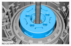
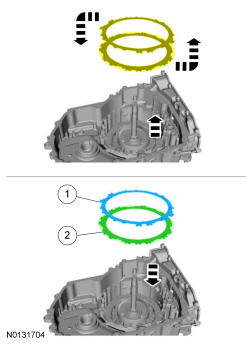
- 171.
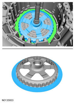
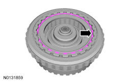
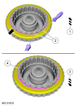
Using the special tool and a press, compress the overdrive (4, 5, 6) clutch return spring and remove the snap ring.
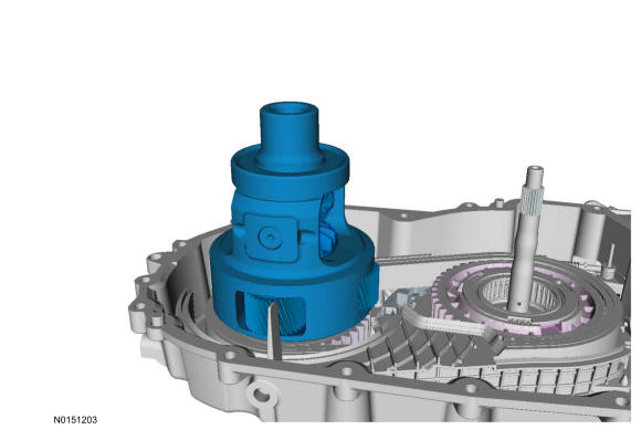
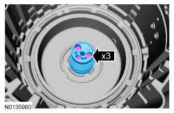
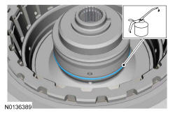
- 174.
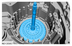
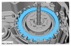
Install the clutch support tower in the transmission case and install the clutch support tower bolts.- Tighten to 12 Nm (106 lb-in).
- 178.
Apply compressed air to the overdrive (4, 5, 6) clutch piston port and remove the overdrive (4, 5, 6) clutch piston.
- 180.
Remove and discard the overdrive (4, 5, 6) clutch piston seal from the overdrive/direct clutch assembly.
- 182.
Install the special tools on the direct (3, 5, R) clutch cylinder. Using a press, compress the direct (3, 5, R) clutch piston return spring, and remove the snap ring.- 1.
Do not contact the overdrive/direct clutch hub and shaft assembly with the direct (3, 5, R) clutch cylinder.
- 2.
Remove the snap ring.
- 1.
NOTE:
Only compress the direct clutch piston return spring far enough to take the tension from the direct clutch cylinder off the snap ring. If the piston is compressed too far, the piston alignment tab may be broken off.
- 185.
Remove the direct (3, 5, R) clutch piston return spring.
NOTE:
Note the position of the return spring for assembly. The flat side faces down.
- 186.
Remove the direct (3, 5, R) clutch snap ring.- 1.
Slightly lift up on the clutch so that the snap ring floats freely.
- 2.
Compress the snap ring.
- 3.
Allow the clutch and pressure plate to drop so that the snap ring is out of the pressure plate groove.
- 4.
Remove the snap ring.
- 1.
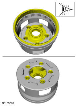
- 190.
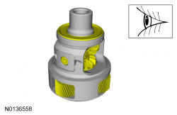
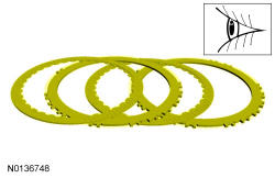
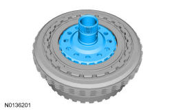
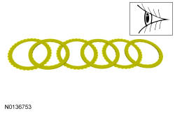
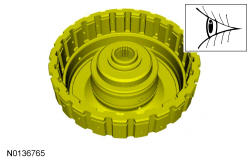
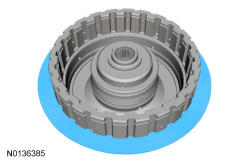
Clean and inspect the overdrive/direct clutch assembly for damage or excessive wear and install new components as necessary.
- 195.
Install the direct (3, 5, R) clutch snap ring.- 1.
Compress the snap ring.
- 2.
Lift the direct (3, 5, R) clutch so that the snap ring is in the groove of the pressure plate.
- 3.
Release the tension on the snap ring.
- 1.
- 199.
Install the special tools on the direct (3, 5, R) clutch cylinder. Using a press, compress the direct (3, 5, R) clutch piston return spring, and install the snap ring.- 1.
Do not contact the overdrive/direct clutch hub and shaft assembly with the direct (3, 5, R) clutch cylinder.
- 2.
Install the snap ring.
- 1.
NOTE:
Only compress the direct clutch piston return spring far enough to take the tension from the direct clutch cylinder off the snap ring. If the piston is compressed too far, the piston alignment tab may be broken off.
- 200.
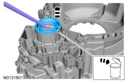
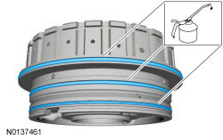
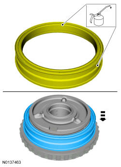
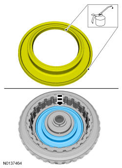
Install new seals on the overdrive (4, 5, 6) clutch piston and lubricate the seals with petroleum jelly.
- 201.
Install a new overdrive (4, 5, 6) clutch piston inner seal and lubricate the seal with petroleum jelly.
- 203.
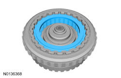
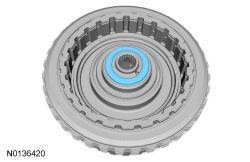
Using the special tools, install the overdrive (4, 5, 6) clutch piston into the overdrive/direct clutch assembly by hand.
- 204.
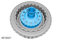
Install the overdrive (4, 5, 6) clutch piston return spring.
NOTE:
Holes face up on the overdrive (4, 5, 6) clutch piston return spring.

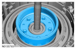
- 216.
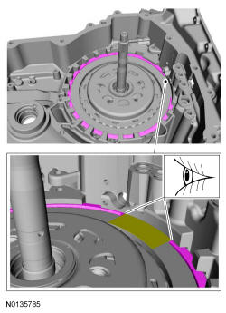
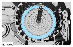
Position the overdrive/direct clutch assembly in the transmission case, install the special tool or a dial indicator and position the plunger on the overdrive (4, 5, 6) clutch pressure plate.
- 217.
Apply 483 kPa (70 psi) of air pressure to the overdrive (4, 5, 6) clutch piston port while recording the clutch pack clearance on the Dial Indicator. The clearance should be between 0.950 mm (0.037 in) and 1.778 mm (0.07 in). If the clearance is out of range, check the overdrive (4, 5, 6) clutch pack for correct installation. If the overdrive (4, 5, 6) clutch pack is correctly installed, install a new overdrive (4, 5, 6) clutch pack.
NOTE:
The dial indicator plunger is positioned on the overdrive (4, 5, 6) clutch pressure plate.
- 218.
Position the plunger on one of the top direct (3, 5, R) clutch plate tabs. Apply 483 kPa (70 psi) of air pressure to the direct (3, 5, R) clutch piston port while recording the clutch pack clearance on Dial Indicator. The clearance should be between 1.71 mm (0.067 in) and 3.61 mm (0.142 in). If the clearance is out of range, check the direct (3, 5, R) clutch pack for correct installation. If the direct (3, 5, R) clutch pack is correctly installed, install a new direct (3, 5, R) clutch pack.
- 219.
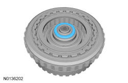
Remove the special tool, overdrive/direct clutch assembly and the No. 1 overdrive/direct clutch assembly thrust bearing.
- 226.
Install the intermediate (2, 6) clutch piston on the seal protector with the bleed hole aligned at the top of the transmission case.
NOTE:
Be sure the bleed hole is aligned in the correct position as noted during disassembly or damage to the transmission can occur.
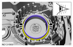
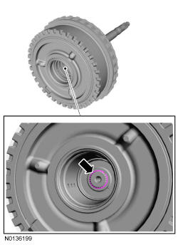
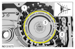
- 227.
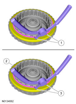
Position the clutch piston return spring on the piston to align the piston before pushing it in its bore. The tabs of the return spring should fit into the indentions of the piston and the 2 outer tabs should be at the clockwise most position of the open area at the bottom of the transmission case. The bleed hole on the piston should be aligned between the inner double tabs of the return spring.- 1.
Inner double tabs
- 2.
Bleed hole
- 3.
Outer tabs
- 1.
- 229.
Install the special tool on the intermediate (2, 6) clutch piston. Push the intermediate (2, 6) clutch piston into the clutch cylinder by hand.
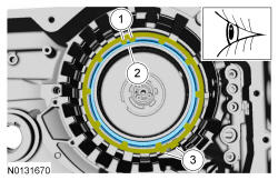
- 230.
The tabs of the return spring should fit into the indentions of the piston and the 2 outer tabs should be at the clockwise most position of the slot at the bottom of the case. The bleed hole on the piston should be aligned between the inner double tabs of the return spring.- 1.
Inner double tabs
- 2.
Bleed hole
- 3.
Outer tabs
- 1.
NOTE:
Be sure the return spring is positioned correctly with the forward clutch bleed hole aligned between the inner double tabs and the outer tab in the clockwise most position of the slot at the bottom of the case or damage to the transmission can occur.
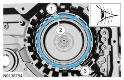
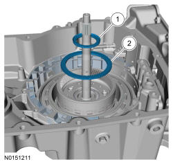
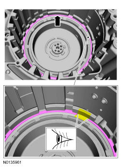
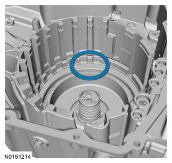
- 231.
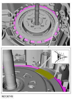
Align the gap of the snap ring to face the front of the transmission.- 1.
Snap ring
- 2.
Snap ring gap
- 3.
Low/reverse and forward (1, 2, 3, 4) clutch hydraulic ports (located at the front of the transmission case)
- 1.
NOTE:
Be sure the snap ring is aligned with the gap facing the front of the transmission or damage to the transmission can occur. The front of the transmission is where the low/reverse and forward (1, 2, 3, 4) clutch hydraulic ports are located.
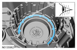
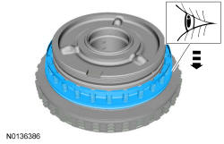
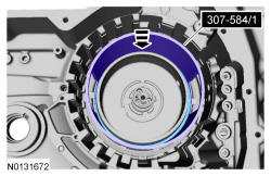
- 232.
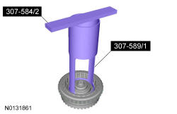
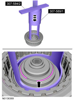
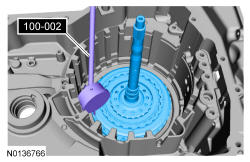
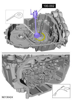
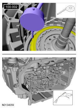
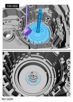
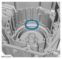
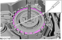
Install the special tool on the transmission case to center the intermediate (2, 6) clutch return spring.
- 235.
Using the special tools, install the intermediate (2, 6) clutch snap ring in the groove.
NOTE:
Be sure the return spring is centered or it can bind on the snap ring groove and cause damage to the transmission case.
- 237.
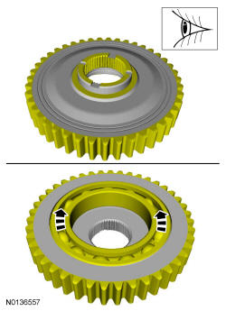
Install the No. 1 thrust bearing with the flat side facing up.
NOTE:
Be sure to install the No. 1 thrust bearing with the flat side facing up or damage to the transmission can occur.
- 239.
Install the No. 3 thrust bearing with the flat side facing down.
NOTE:
Be sure to install the No. 3 thrust bearing with the flat side facing down or damage to the transmission can occur.
- 243.
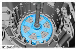
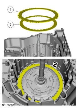
Install the intermediate (2, 6) clutch assembly, temporarily reversing the top friction and steel plates for the clutch stack-up measurement.- 1.
Steel plate
- 2.
Friction plate
- 1.
- 245.
Using a depth gauge, measure and record as measurement A, the distance from the special tool to the top of the intermediate (2, 6) clutch pack at 3 different points and average the 3 distances.
- 246.
Using a depth gauge, measure and record as measurement B, the distance from the top of the special tool to the transmission case step above the intermediate (2, 6) clutch.
- 247.
Subtract measurement B from measurement A The clearance should be between 0.240 mm (0.009 in) and 2.60 mm (0.102 in). If the clearance is out of range, check the intermediate (2, 6) clutch pack for correct installation. If the intermediate (2, 6) clutch pack is correctly installed, install a new clutch pack.Description Reading Measurement A Measurement B Subtract measurement B from measurement A and check to see if it is within range of 0.240 mm (0.009 in) and 2.60 mm (0.102 in)
- 248.
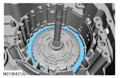
Remove the top intermediate (2, 6) clutch friction and steel plate and correctly install the plates back in the transmission case.- 1.
Friction plate
- 2.
Steel plate
- 1.
NOTE:
When the intermediate (2, 6) clutch is correctly installed, a friction plate is on top.
- 251.
Position the low/reverse pressure plate so that the center support legs fit through the pressure plate and rest on the OWC and install the low/reverse pressure plate.
NOTE:
Note the position of the pressure plate. When installing the center support, the long support legs must fit through the pressure plate and rest on the OWC.
- 253.
Align the low/reverse clutch pack with the pressure plate and install it in the transmission case temporarily reversing the wave spring and top steel plate.- 1.
Steel plate.
- 2.
Wave spring.
- 1.
- 255.
Using a depth gauge, measure and record as measurement A, the distance from the top of the special tool to the contact surface of the low/reverse clutch piston.
- 256.
Using a depth gauge, measure and record as measurement B, the distance from the top of the special tool to the leg surface of the center support.
- 257.
Subtract measurement B from measurement A and record as measurement C.Description Reading Measurement A Measurement B Subtract measurement B from measurement A and record as measurement C.
- 259.
Using a depth micrometer, measure and record as measurement D, the distance from the special tool to the top of the OWC.
- 260.
Using a depth gauge, measure and record as measurement E, the distance from the top of special tool to the top of the low/reverse clutch at 3 different points and average the 3 distances.
- 261.
Subtract measurement E from measurement D and record as measurement F.Description Reading Measurement D Measurement E Subtract measurement E from measurement D and record as measurement F
- 262.
Subtract measurement F from measurement C to get the low/reverse clutch clearance. The clearance should be between 0.406 mm (0.015 in) and 2.000 mm (0.078 in). If the clearance is out of range, check the low/reverse clutch pack for correct installation. If the low/reverse clutch pack is correctly installed, install a new clutch pack.Description Reading Measurement C Measurement F Subtract measurement F from measurement C and check to see if it is within range of 0.406 mm (0.015 in) and 2.000 mm (0.078 in)
- 263.
Remove the top low/reverse clutch steel plate and wave spring and correctly install the plates back in the transmission case.- 1.
Wave spring
- 2.
Steel plate
- 1.
NOTE:
When the low/reverse clutch is correctly installed, the wave spring is on top.
- 264.
Install the center support with the long legs facing down and the feed holes aligned with the feed holes in the transmission case.- 1.
Long center support legs face down
- 2.
Feed holes face the front of the transmission case.
- 1.
NOTE:
Be sure the center support is installed with the long support legs facing down and the feed holes facing the front of the transmission.
- 274.
Install the forward (1, 2, 3, 4) clutch beveled snap ring with the flat side down with the gap facing the front of the transmission.
NOTE:
Be sure to install the forward (1, 2, 3, 4) clutch beveled snap ring with the flat side facing down or the snap ring can come loose, causing damage to the transmission.
- 276.
Install the special tool or a dial indicator on the transmission case and position the plunger on the top forward (1, 2, 3, 4) clutch friction plate.
- 277.
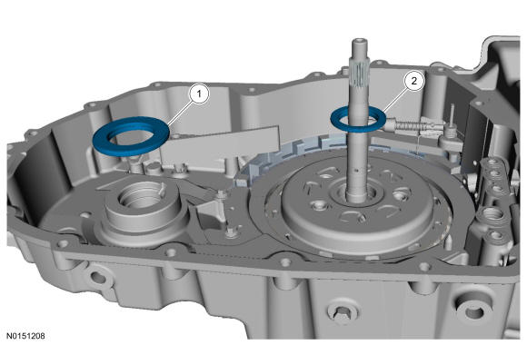
Install the new low/reverse and forward (1, 2, 3, 4) clutch main control-to-transmission case seals.
- 278.
Apply 483 kPa (70 psi) of air pressure to the forward (1, 2, 3, 4) clutch piston port while recording the clutch pack clearance on the dial indicator. The clearance should be between 0.076 mm (0.002in) and 1.840 mm (0.072 in). If the clearance is out of range, check the forward (1, 2, 3, 4) clutch pack for correct installation and the transmission for correct assembly. If the forward (1, 2, 3, 4) clutch pack is correctly installed, install a new forward (1, 2, 3, 4) clutch pack.
- 282.
Install the park pawl actuator rod in the TR sensor. Position the park pawl aside and position the park pawl actuator rod and the TR sensor in the transmission case.
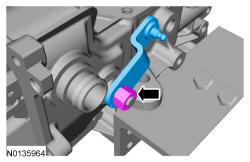
- 285.
Install the manual control lever and the manual control lever nut.- Tighten to 24 Nm (18 lb-ft).
NOTE:
Make sure to hold the manual control lever while tightening the manual control lever nut or damage to the manual control lever and park components will occur.
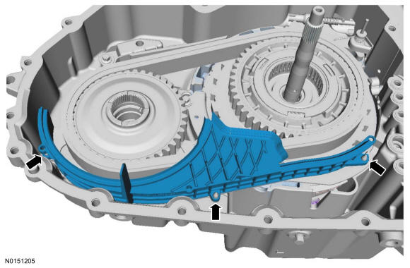
- 287.
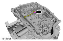
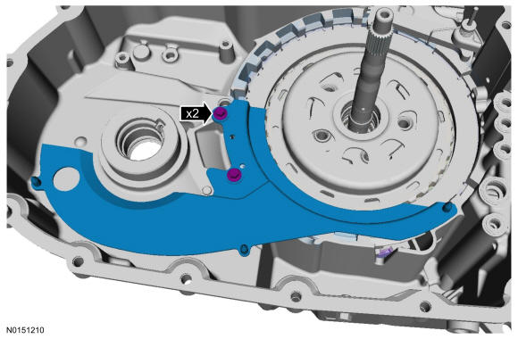
Position the transmission fluid baffle in place and install the transmission fluid baffle bolts.- Tighten to 12 Nm (106 lb-in).
- 288.
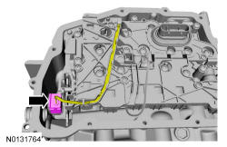
Position the fluid reservoir in place and install the fluid reservoir bolts.- Tighten to 12 Nm (106 lb-in).
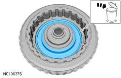
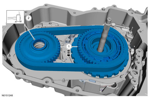
- 290.
- 1.
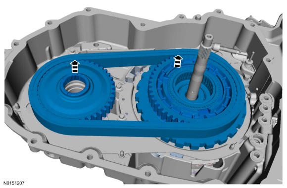
Simultaneously install the drive/driven sprocket and chain assembly.
- 2.
Lightly tap on the driven sprocket to be sure it is fully seated in the case.
- 1.
- 297.
FWD Vehicles. Assemble the special tools and install a new RH halfshaft seal on the special tool.
- 299.
AWD Vehicles. Assemble the special tools and install a new RH halfshaft seal on the special tool.
- 301.
Install the pump and filter assembly in the torque converter housing and install the pump-to-torque converter housing bolts.- Tighten to 35 Nm (26 lb-ft).
- 302.
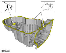
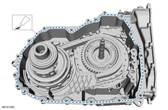
Apply a bead of the Ultra Silicone Sealant.
NOTE:
Be sure the sealing surfaces of the torque converter housing and the transmission housing are free of oil before applying silicone.
- 304.
Install the torque converter housing bolts and the torque converter housing stud bolt.- Tighten to 24 Nm (18 lb-ft).
NOTE:
Be sure the torque converter housing stud bolt is in the correct location as noted during disassembly.
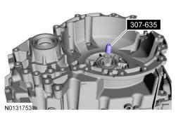
- 308.
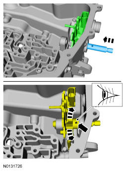
Install the new main control-to-transmission case separator plate and align it on the stud and the guide pin.
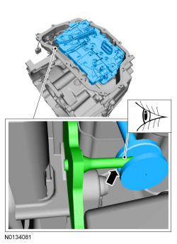
- 309.
Position the main control assembly in place and align the manual valve on the TR sensor.
NOTE:
Be sure that the manual pin (part of the TR sensor) is correctly installed in the manual valve.
- 313.
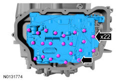
Tighten the main control-to-transmission case bolts and the main control nut in a crisscross pattern.- Tighten to 10 Nm (89 lb-in).
- 314.
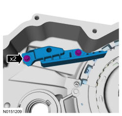
Position the TR sensor detent spring in place with the alignment tab in the alignment hole and install the TR sensor detent spring bolt.- Tighten to 13 Nm (115 lb-in).
- 315.
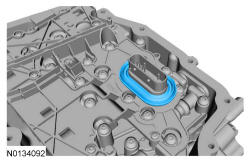
Install the main control-to-cover seal.
NOTE:
Be sure the main control-to-cover seal is installed with the holes facing up.
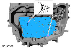
- 318.
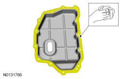
Make sure that the mating faces are clean and free of foreign material. Refer to RTV Sealing Surface Cleaning and Preparation in Engine System General Information .
NOTE:
Do not use metal scrapers, wire brushes, power abrasive discs, or other abrasive means to clean sealing surfaces. These tools cause scratches and gouges which make leak paths.
- 319.
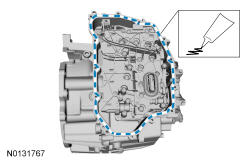
Apply a bead of the Ultra Silicone Sealant.
NOTE:
Be sure the sealing surface is free of oil before applying silicone.
- 320.
Install the main control cover and the main control cover bolts and stud bolts.- Tighten to 12 Nm (106 lb-in).
NOTE:
Install the main control cover stud bolts in the correct location as noted during disassembly.
- 321.
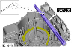
Using the special tools, install the torque converter.
NOTE:
The torque converter is heavy. Be careful not to drop it or damage will result.