Removal And Installation: Camshaft: Removal
- With the vehicle in NEUTRAL, position it on a hoist. REFER to JACKING AND LIFTING , Lifting Points.
- Recover the A/C system. REFER to CLIMATE CONTROL DATC .
- Remove the cowl panel. REFER to FRONT END BODY PANELS .
- Release the fuel system pressure. REFER to FUEL SYSTEM PRESSURE RELEASE .
- Remove the engine ACL assembly and ACL outlet pipe. REFER to INTAKE AIR DISTRIBUTION AND FILTERING .
- Remove the battery tray. REFER to BATTERY, MOUNTING AND CABLES .
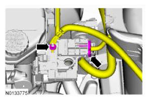
- Remove the nut and disconnect the 2 battery feed cables from the positive battery terminal.
- Remove the retainer and the ground wire cable.
- Remove the retainer and the ground wire cable.
- Disconnect the engine wiring harness electrical connector.
- Remove the front wheels and tires. REFER to WHEELS AND TIRES .
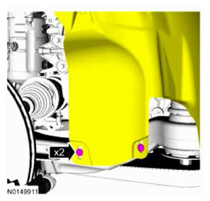
-
NOTE: RH shown in illustration, LH similar.
Remove the 2 RH and 2 LH lower pin-type retainers from the engine splash shields and position the shields aside.
- Remove the accessory drive belt. REFER to ACCESSORY DRIVE BELT .
- Drain the cooling system. REFER to ENGINE COOLING .
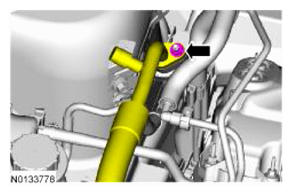
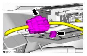
- Remove the nut and disconnect the A/C tube.
- Disconnect the A/C pressure switch electrical connector.
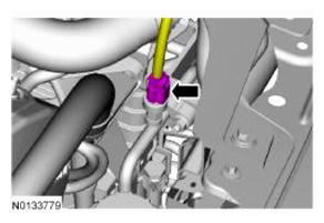
- Remove the nut and disconnect the A/C tube.
- Remove degas bottle. REFER to ENGINE COOLING .
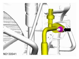
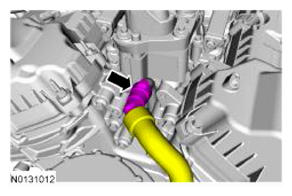
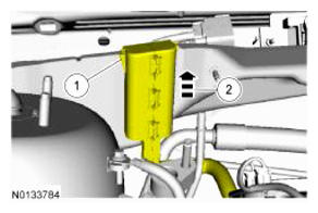
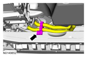
- Disconnect the degas bottle coolant hose from the engine coolant tube.
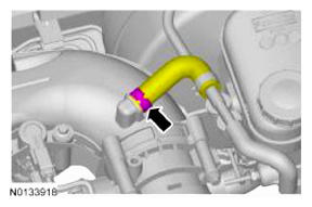
- Disconnect the brake booster vacuum hose from the upper intake manifold.
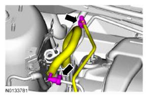
- Disconnect the EVAP
tube and the fuel supply tube quick connect coupling. REFER to
FUEL SYSTEM GENERAL INFORMATION
.
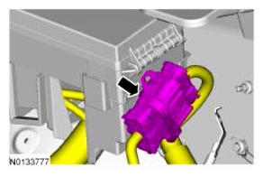
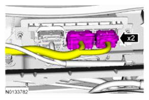
- Disconnect the 2 PCM
electrical connectors.
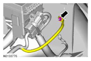
- Disconnect the engine harness electrical connector.
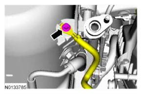
- Remove the engine wiring harness retainer from the bulkhead.
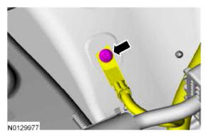
- Remove the bolt and ground wire from the RH shock tower.
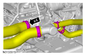
- Disconnect the upper radiator hose, lower radiator hose and 2 heater hoses from the thermostat housing.
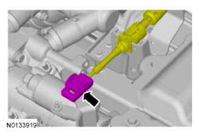
- Disconnect the transaxle control cable from the control lever.
- Disconnect the transaxle control cable from the shift cable bracket.
- If equipped, detach the engine block heater harness.
-
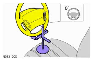
NOTE: Use a steering wheel holding device (such as Hunter® 28-75-1 or equivalent).
Using a suitable holding device, hold the steering wheel in the straight-ahead position.
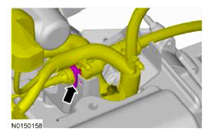
- Remove the 3 twist lock retainers and the underbody air duct.
-
NOTE: Do not allow the intermediate shaft to rotate while it is disconnected from the gear or damage to the clockspring may occur. If there is evidence that the intermediate shaft has rotated, the clockspring must be removed and recentered. For additional information, refer to SUPPLEMENTAL RESTRAINT SYSTEM .NOTE: Index-mark the steering column shaft position to the steering gear for reference during installation.
Remove the bolt and disconnect the steering column shaft from the steering gear.
- Remove the exhaust Y-pipe. For additional information, refer to EXHAUST SYSTEM .
-
NOTE: Index-mark the driveshaft for installation.
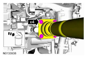
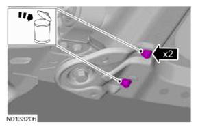
If equipped with All-Wheel Drive (AWD), remove and discard the 4 bolts and support the driveshaft with a length of mechanic's wire.
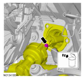
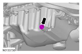
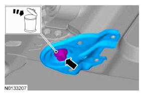
- Remove the drain plug and drain the engine oil.
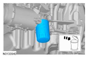
- Remove and discard the engine oil filter.
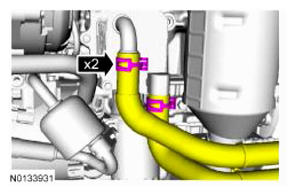
- If equipped, disconnect the 2 PTU cooler hoses. For additional information, refer to
FUEL SYSTEM GENERAL INFORMATION
.
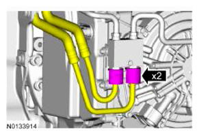
- If equipped, disconnect the oil cooler coolant hoses.
- If equipped, unlatch the cooler hose retainer latch and pry up on the oil cooler hose retainer to release the retainer and remove it from the subframe.
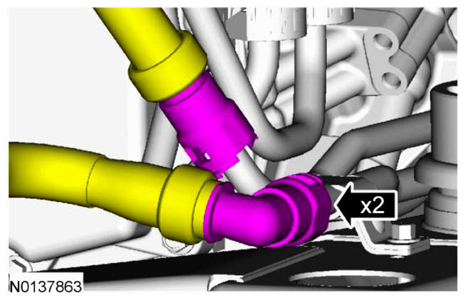
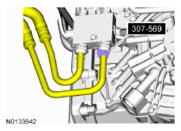
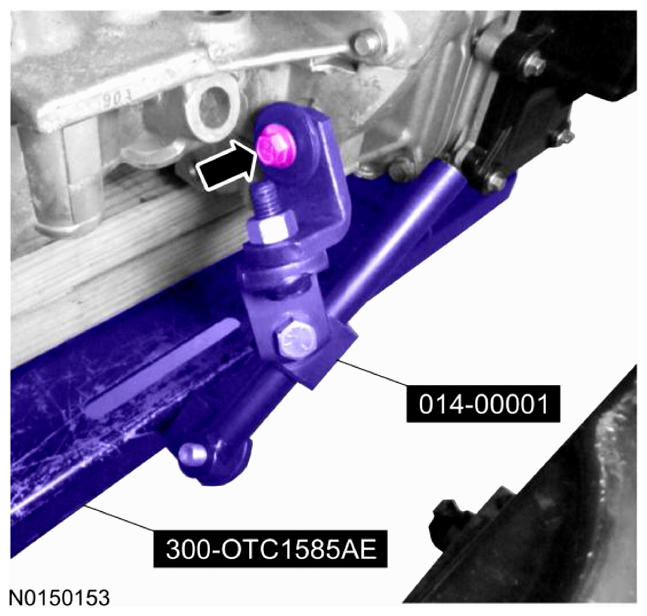
- Remove the 2 secondary latches from the transmission fluid cooler tubes at the transmission fluid cooler thermal bypass valve.
- Using 307-569, disconnect the transmission fluid cooler tubes from the transmission fluid cooler thermal bypass valve.
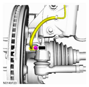
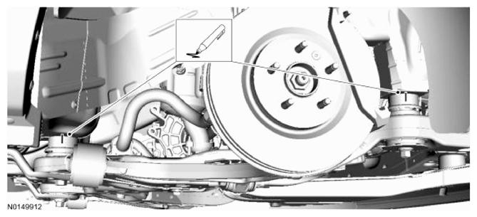
-
NOTE: LH shown in illustration, RH similar.
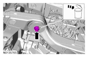
Remove the bolt and the wheel speed sensor.
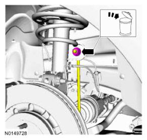
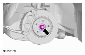
-
NOTE: LH shown in illustration, RH similar.
Remove and discard the upper stabilizer link nut.
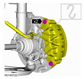
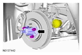
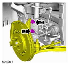
-
NOTE: Do not allow the brake caliper to hang from the brake flexible hose or damage to the hose may occur.NOTE: LH shown in illustration, RH similar.
Remove the brake caliper guide pin bolts and calipers.
-
NOTE: RH shown in illustration, LH similar.
Using a wax pencil, mark the relationship of the front and rear subframe to the underbody at the mounting locations on both side.
-
NOTE: LH shown in illustration, RH similar.
Remove the LH and RH halfshaft nuts.
-
NOTE: LH shown in illustration, RH similar.
Separate the LH and RH halfshaft from the wheel hubs.
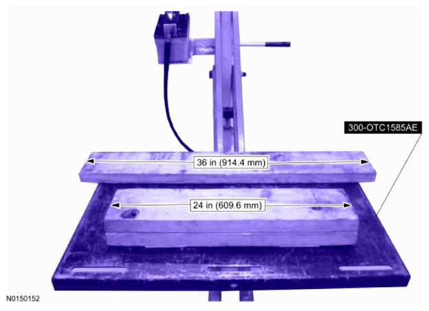
- Position a 2 x 6 board, 36 in (914.4 mm) in length and two 2 x 6 boards 24 in (609.6 mm) in length onto the powertrain lift.
- Install the Adjustable Grip Arm from the powertrain lift table to the LH engine-to-transmission bolt hole.
- Install a ratchet strap from the front of the subframe under the powertrain lift table to the rear of the subframe, to secure the subframe to the powertrain lift table.
-
NOTE: LH shown in illustration, RH similar.NOTE: The halfshafts are not being remove from the transmission.
Remove the strut-to-wheel knuckle nuts and bolts.
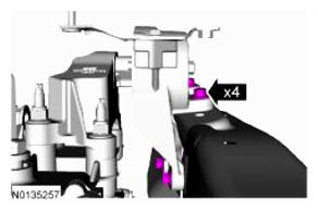
- Remove the 4 transmission support insulator-to-frame rail bolts.
- Remove the 3 nuts, the bolt and the transaxle support insulator assembly.
- Remove the 4 engine mount nuts, the 3 engine mount bolts and the engine mount.
-
NOTE: RH shown in illustration, LH similar.
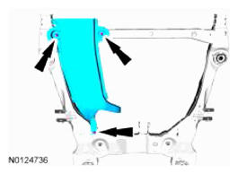
Remove the subframe bracket-to-body bolts.
-
NOTE: RH shown in illustration, LH similar.
Remove the rear subframe bolts and the subframe brackets.
-
NOTE: RH shown in illustration, LH similar.
Remove the front subframe bolts.
- Lower the subframe and powertrain assembly from the vehicle.
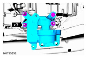
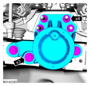
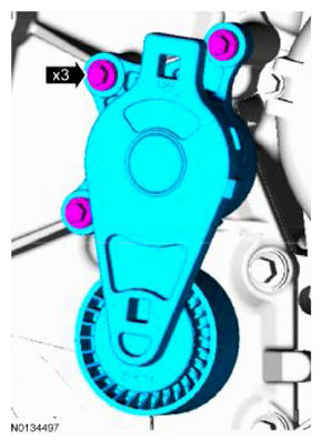
- Remove the 3 bolts and the accessory drive belt tensioner.
- Remove the crankshaft front seal. Refer to CRANKSHAFT FRONT SEAL .
- Remove the crankcase vent tube. REFER to
FUEL SYSTEM GENERAL INFORMATION
.
-
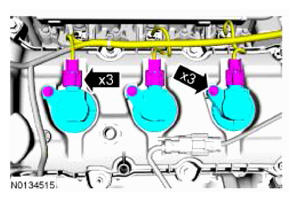
NOTE: When removing the ignition coil-on-plugs, a slight twisting motion will break the seal and ease removal.
Disconnect the 3 LH coil-on-plug electrical connectors and remove the 3 bolts and the 3 LH coil-on-plugs.
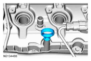
- Remove the oil level indicator.
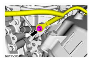
- Remove the ground wire bolt from the engine front cover.
- Remove the engine wiring harness from the LH valve cover.
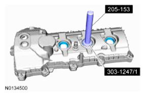
-
NOTE: When removing valve cover do not apply excessive force to the VCT oil control solenoid.NOTE: If the VCT solenoid seal sticks to the VCT oil control solenoid, then carefully wiggle the valve cover until the bond breaks free.NOTE: The plastic electrical connector on the VCT oil control solenoid will rotate approximately 12 degrees inside the steel housing, which is normal.
Loosen the 4 bolts and 7 stud bolts and remove the LH valve cover.
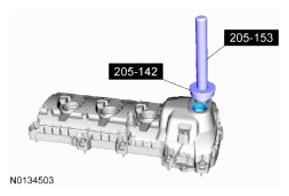
- Inspect the 2 VCT solenoid seals. Remove any damaged seals.
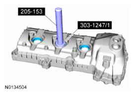
- Inspect the spark plug tube seals. Remove any damaged seals.
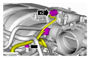
- Disconnect the EVAP canister purge valve and throttle body electrical connectors.
- Disconnect the EVAP vapor tube from the EVAP canister purge valve. REFER to FUEL SYSTEM GENERAL INFORMATION .
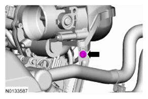
- Disconnect the crankcase ventilation hose from the upper intake manifold.
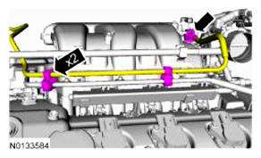
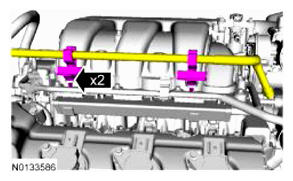
- Detach the 2 coolant tube retainers from the upper intake manifold.
- Remove the upper intake manifold support bracket bolt.
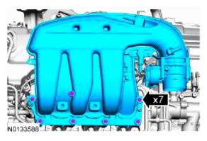
- Remove the 7 bolts and the upper intake manifold.
-
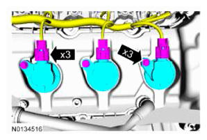
NOTE: When removing the ignition coil-on-plugs, a slight twisting motion will break the seal and ease removal.
Disconnect the 3 RH coil-on-plug electrical connectors and remove the 3 bolts and the 3 RH coil-on-plugs.
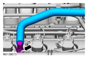
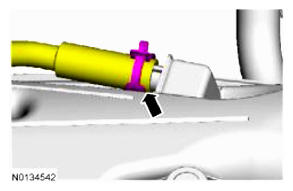
- Remove the PCV
crankcase vent tube.
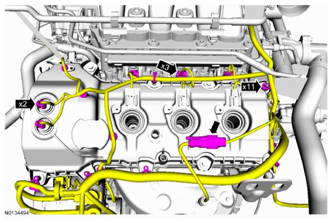
- Remove the engine wiring harness from the RH valve cover.
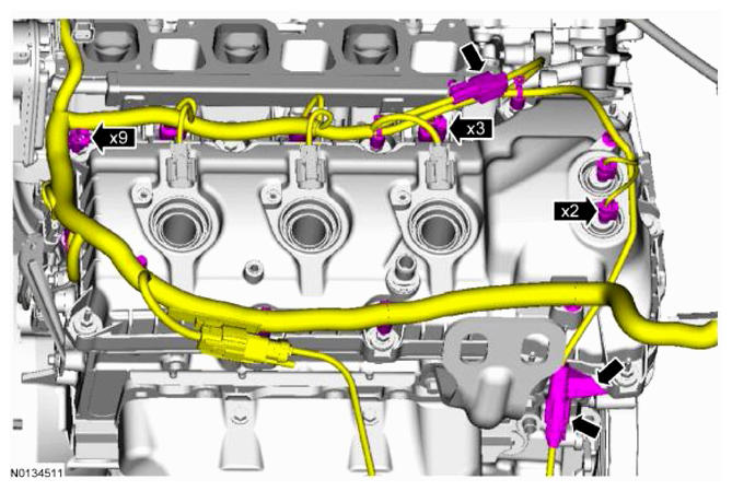
- Disconnect the 2 VCT oil control solenoid electrical connectors.
- Detach and disconnect the RH CMS electrical connector.
- Disconnect the 3 fuel injector electrical connectors.
- Disconnect the CHT sensor wiring harness jumper electrical connector.
- Detach the 9 wiring harness retainers from the RH valve cover and stud bolts and position the harness aside.
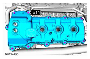
-
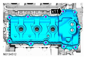
NOTE: When removing valve cover do not apply excessive force to the VCT oil control solenoid.NOTE: If the VCT solenoid seal sticks to the VCT oil control solenoid, then carefully wiggle the valve cover until the bond breaks free.NOTE: The plastic electrical connector on the VCT oil control solenoid will rotate approximately 12 degrees inside the steel housing, which is normal.
Loosen the 11 retainers and remove the RH valve cover.
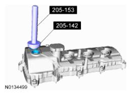
- Inspect the 2 VCT solenoid seals. Remove any damaged seals.
- Inspect the spark plug tube seals. Remove any damaged seals.
-
NOTE: It may be necessary to use the floor jack and lower the engine slightly to gain enough access to remove the bolt.
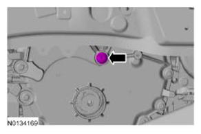
Remove the lower M10 engine front cover bolt.
-
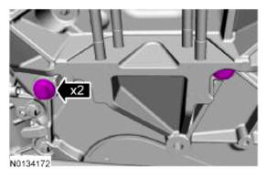
NOTE: It may be necessary to use the floor jack and raise the engine slightly to gain enough access to remove the bolts.
Remove the 2 M10 engine front cover bolts.
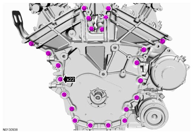
- Remove the 22 M8 engine front cover bolts.
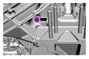
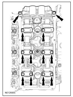
- Remove the M6 engine front cover bolt.
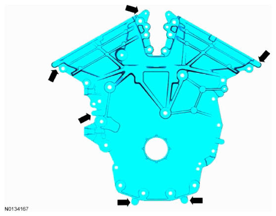
- Using a suitable pry tool, locate the 7 pry pads shown in illustration and pry the engine front cover loose and remove.
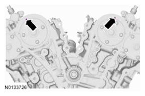
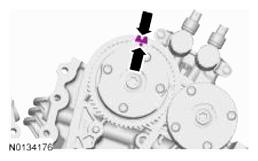
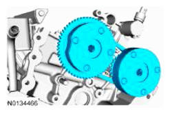
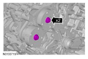
- Rotate the crankshaft clockwise and align the timing marks on the intake VCT
assemblies as shown in illustration.
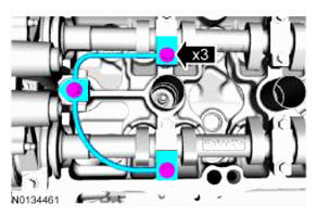
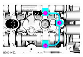
- Remove the 3 bolts and the LH valve train oil tube.
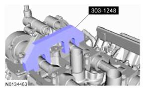
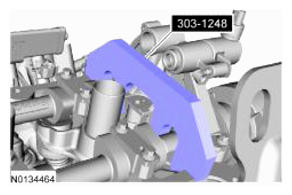
-
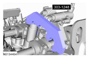
NOTE: The 303-1248 will hold the camshafts in the TDC position.
Install 303-1248 onto the flats of the LH camshafts.
- Remove the 3 bolts and the RH valve train oil tube.
-
NOTE: The 303-1248 will hold the camshafts in the TDC position.
Install 303-1248 onto the flats of the RH camshafts.
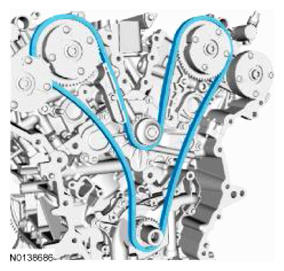
-
NOTE: The following 3 steps are for primary timing chains that the colored links are not visible.
Mark the timing chain link that aligns with the timing mark on the LH intake VCT assembly as shown in illustration.
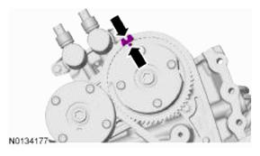
- Mark the timing chain link that aligns with the timing mark on the RH intake VCT
assembly as shown in illustration.
-
NOTE: The crankshaft sprocket timing mark should be between the 2 colored links.
Mark the 2 timing chain links that align with the timing mark on the crankshaft sprocket as shown in illustration.
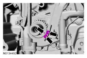
- Remove the 2 bolts and the primary timing chain tensioner.
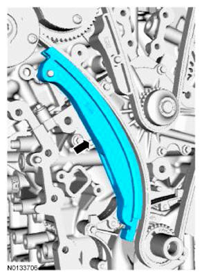
- Remove the primary timing chain tensioner arm.
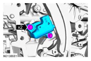
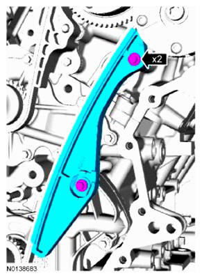
- Remove the 2 bolts and the lower LH primary timing chain guide.
-
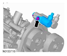
NOTE: Removal of the VCT oil control solenoid will aid in the removal of the primary timing chain.NOTE: A slight twisting motion will aid in the removal of the VCT oil control solenoid.NOTE: Keep the VCT oil control solenoid clean of dirt and debris.
Remove the bolt and the LH intake VCT oil control solenoid.
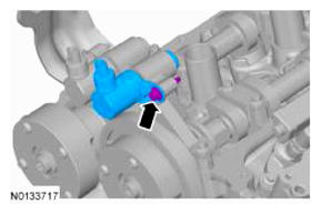
-
NOTE: Removal of the VCT oil control solenoid will aid in the removal of the primary timing chain.NOTE: A slight twisting motion will aid in the removal of the VCT oil control solenoid.NOTE: Keep the VCT oil control solenoid clean of dirt and debris.
Remove the bolt and the RH intake VCT oil control solenoid.
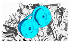
- Remove the primary timing chain.
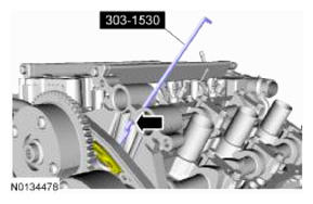
-
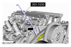
NOTE: The following steps are to remove the LH camshafts.NOTE: The 2 VCT oil control solenoids are removed for clarity.NOTE: The 303-1530 is inserted through a hole in the top of the mega cap.
Compress the LH secondary timing chain tensioner and install the 303-1530 in the hole on the rear of the secondary timing chain tensioner guide and let it hold against the mega cap to retain the tensioner in the collapsed position.
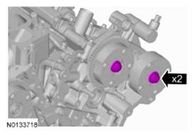
- Remove and discard the 2 LH VCT
assembly bolts.
- Remove the 2 LH VCT assemblies and secondary timing chain.
-
NOTE: When the 303-1248 is removed, valve spring pressure may rotate the LH camshafts approximately 3 degrees to a neutral position.
Remove the 303-1248 from the LH camshafts.
-
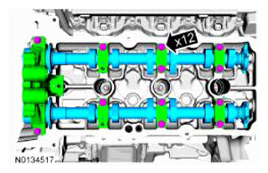
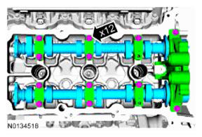
NOTE: Cylinder head camshaft bearing caps are numbered to verify that they are assembled in their original positions.NOTE: Mark the exhaust and intake camshafts for installation into their original locations.
Remove the 12 bolts, 6 camshaft caps, mega cap and the LH camshafts.
-
NOTE: The following steps are to remove the RH camshafts.NOTE: The 2 VCT oil control solenoids are removed for clarity.NOTE: The 303-1530 is inserted through a hole in the top of the mega cap.
Compress the RH secondary timing chain tensioner and install the 303-1530 in the hole on the rear of the secondary timing chain tensioner guide and let it hold against the mega cap to retain the tensioner in the collapsed position.
- Remove and discard the 2 RH VCT
assembly bolts.
- Remove the 2 RH VCT assemblies and secondary timing chain.
-
NOTE: When the 303-1248 is removed, valve spring pressure may rotate the RH camshafts approximately 3 degrees to a neutral position.
Remove the 303-1248 from the RH camshafts.
-
NOTE: Cylinder head camshaft bearing caps are numbered to verify that they are assembled in their original positions.NOTE: Mark the exhaust and intake camshafts for installation into their original locations.
Remove the 12 bolts, 6 camshaft caps, mega cap and the RH camshafts.