Engine - All Wheel Drive (AWD): Removal
WARNING:
Before beginning any service procedure in this article, refer to Safety Warnings in SERVICE INFORMATION
.
WARNING:
Do not smoke, carry lighted tobacco or have an open flame of any type when working on or near any fuel-related component. Highly flammable mixtures are always present and may be ignited. Failure to follow these instructions may result in serious personal injury.
- 1.
With the vehicle in NEUTRAL, position it on a hoist. REFER to Jacking and Lifting , Lifting Points.
- 2.
Recover the A/C system. REFER to Climate Control DATC .
- 3.
Remove the cowl panel. REFER to Front End Body Panels .
- 4.
Release the fuel system pressure. REFER to Fuel System General Information .
- 5.
Remove the engine ACL assembly and ACL outlet pipe. REFER to Intake Air Distribution and Filtering .
- 6.
Remove the battery tray. REFER to Battery, Mounting and Cables .
- 11.
Remove the front wheels and tires. REFER to Wheels and Tires .
- 12.
Remove the 2 RH and 2 LH lower pin-type retainers from the engine splash shields and position the shields aside.
NOTE:
RH shown, LH similar.
- 13.
Remove the accessory drive belt. REFER to Accessory Drive .
- 14.
Drain the cooling system. REFER to Engine Cooling .
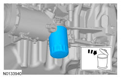
- 18.
Remove degas bottle. REFER to Engine Cooling .

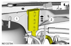
- 21.
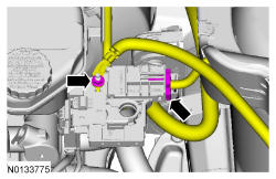
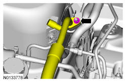
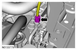
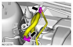
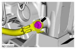
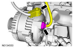
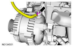
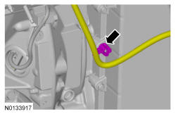
Disconnect the EVAP tube and the fuel supply tube quick connect coupling. REFER to Fuel System General Information .
- 24.
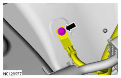
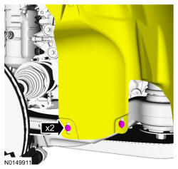
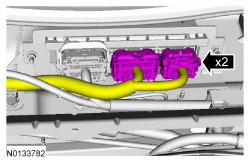
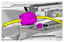
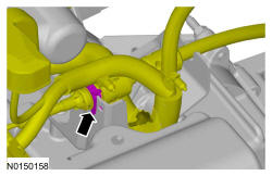
Remove the engine wiring harness retainer from the bulkhead.- Push the wiring harness retainer tab in.
- Slide the wiring harness up and out of the bulkhead.
- 26.
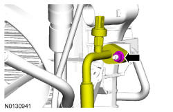
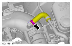
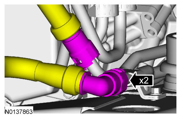
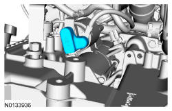
Disconnect the upper radiator hose, lower radiator hose and 2 heater hoses from the thermostat housing.
- 30.
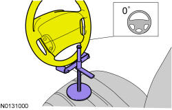
Using a suitable holding device, hold the steering wheel in the straight-ahead position.
NOTE:
Use a steering wheel holding device (such as Hunter ® 28-75-1 or equivalent).
- 32.
Remove the bolt and disconnect the steering column shaft from the steering gear.- Discard the bolt.
NOTE:
Index-mark the steering column shaft position to the steering gear for reference during installation.
NOTE:
Do not allow the intermediate shaft to rotate while it is disconnected from the gear or damage to the clockspring may occur. If there is evidence that the intermediate shaft has rotated, the clockspring must be removed and recentered. For additional information, REFER to Supplemental Restraint System
.
- 33.
Remove the exhaust Y-pipe. For additional information, REFER to Exhaust System .
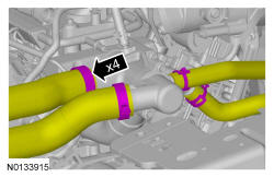
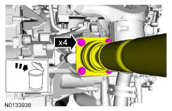
- 34.
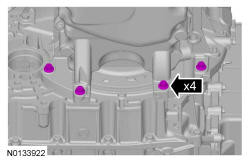
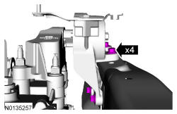
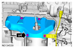
Remove and discard the 4 bolts and support the driveshaft with a length of mechanic's wire.
NOTE:
Index-mark the driveshaft for installation.
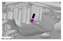
- 35.
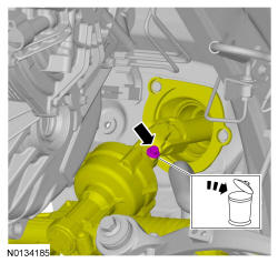
Remove the drain plug and drain the engine oil.- Install the drain plug and tighten to 27 Nm (20 lb-ft).
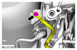
- 40.
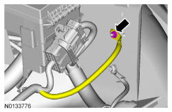
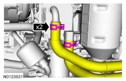
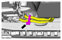
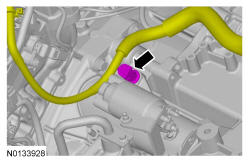
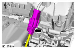
If equipped, disconnect the 2 PTU cooler hoses. For additional information, REFER to Fuel System General Information .
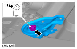
- 42.
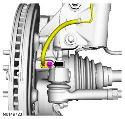
If equipped, unlatch the cooler hose retainer latch and pry up on the oil cooler hose retainer to release the retainer and remove it from the subframe.
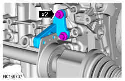
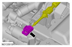
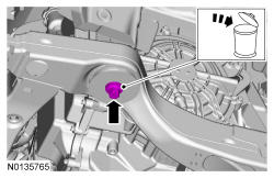
- 43.
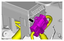
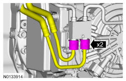
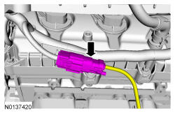
Remove the 2 secondary latches from the transmission fluid cooler tubes at the transmission fluid cooler thermal bypass valve.
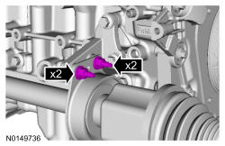
- 44.
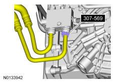
Using 307-569, disconnect the transmission fluid cooler tubes from the transmission fluid cooler thermal bypass valve.
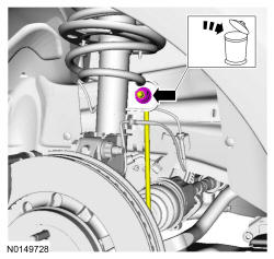
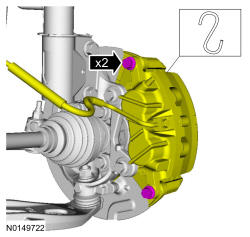
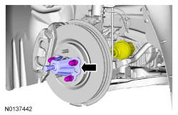
- 47.
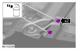
Remove the brake caliper guide pin bolts and calipers.- Support the calipers.
NOTE:
LH shown, RH similar.
NOTE:
Do not allow the brake caliper to hang from the brake flexible hose or damage to the hose may occur.
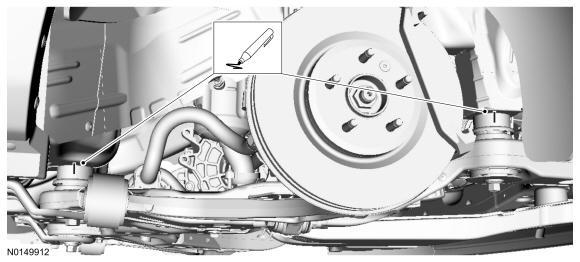
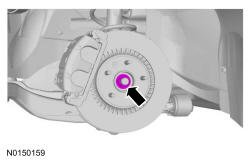
- 48.
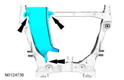
Using a wax pencil, mark the relationship of the front and rear subframe to the underbody at the mounting locations on both side.
NOTE:
RH shown, LH similar.
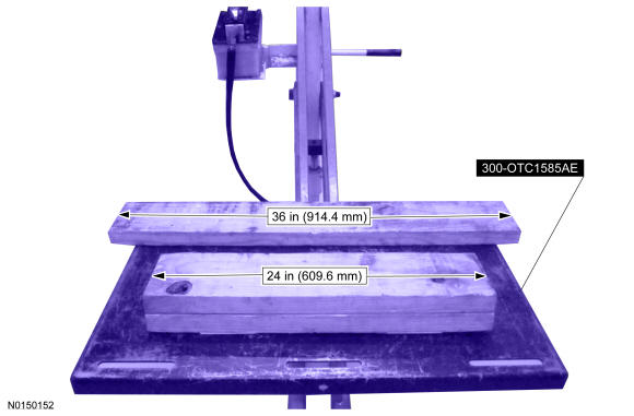
- 51.
Position a 2 x 6 board, 36 in (914.4 mm) in length and two 2 x 6 boards 24 in (609.6 mm) in length onto the powertrain lift.- Position the powertrain lift table with:
- the long board towards the rear of the subframe.
- the short boards under the engine and transmission.
- Position the powertrain lift table with:
- 52.
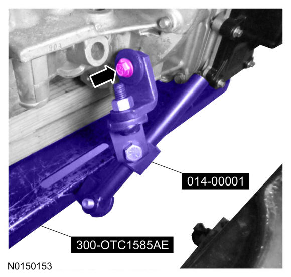
Install the Adjustable Grip Arm from the powertrain lift table to the LH engine-to-transmission bolt hole.
- 53.
Install a ratchet strap from the front of the subframe under the powertrain lift table to the rear of the subframe, to secure the subframe to the powertrain lift table.
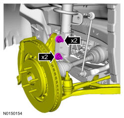
- 54.
Remove the strut-to-wheel knuckle nuts and bolts.- Remove the strut from the wheel knuckle and the halfshafts from the wheel knuckle.
NOTE:
The halfshafts are not being remove from the transmission.
NOTE:
LH shown, RH similar.
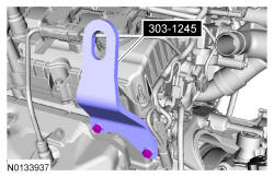


- 72.
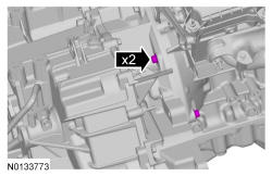
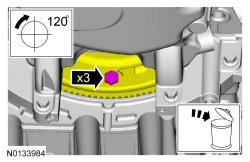
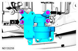
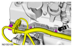
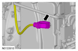
Detach the 3 wiring harness retainer from the valve cover stud bolt and position the harness on transmission.
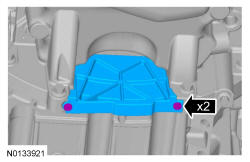
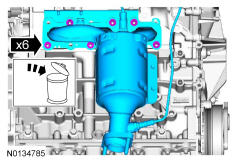
- 78.
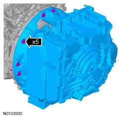
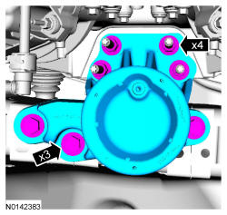
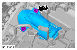
Remove the 6 nuts and the RH catalytic converter manifold.- Discard the nuts and RH catalytic converter manifold gasket.

- 82.
Remove the ratchet strap from the front of the subframe under the powertrain lift table to the rear of the subframe.
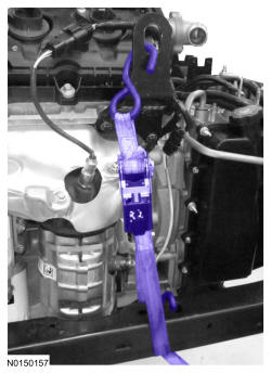
- 83.
Install the ratchet strap from the front subframe to the LH engine lift eye and from the rear of the subframe to the RH engine lift eye.
NOTE:
LH shown, RH similar.
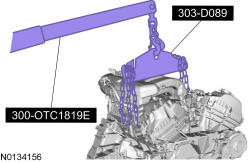
- 84.
Using the Floor Crane and Spreader Bar, remove the powertrain and subframe as an assembly from the powertrain lift table and set on the ground.- Position wood blocks under the engine and transmission.
- 85.
Remove the ratchet strap from the front subframe to the LH engine lift eye and from the rear of the subframe to the RH engine lift eye.
NOTE:
LH shown, RH similar.