Engine - All Wheel Drive (AWD): Installation
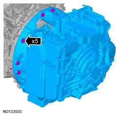
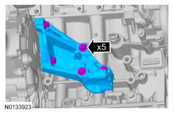
- 2.
Align the transaxle to the engine and install the 5 transaxle-to-engine bolts.- Tighten to 48 Nm (35 lb-ft).
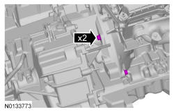
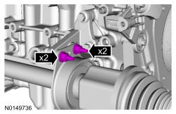
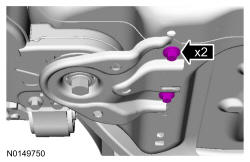
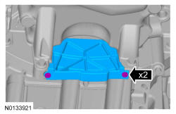
- 5.
Install the 2 intermediate shaft bracket studs and nuts.- Tighten the studs to 10 Nm (89 lb-in).
- Tighten the nuts to 25 Nm (18 lb-ft).
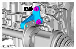
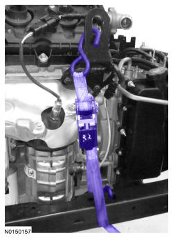
- 6.
Install the ratchet strap from the front subframe to the LH engine lift eye and from the rear of the subframe to the RH engine lift eye.
NOTE:
LH shown, RH similar.
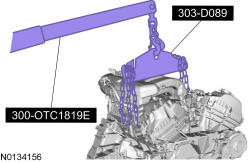
- 7.
Using the Floor Crane and Spreader Bar, install the powertrain and subframe as an assembly on the powertrain lift table.
- 8.
Remove the ratchet strap from the front subframe to the LH engine lift eye and from the rear of the subframe to the RH engine lift eye.
NOTE:
LH shown, RH similar.

- 10.
Install a ratchet strap from the front of the subframe under the powertrain lift table to the rear of the subframe, to secure the subframe to the powertrain lift table.
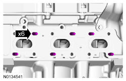
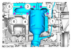
- 13.
Using a new gasket, install the RH exhaust manifold and 6 new nuts. Tighten in 2 stages in the sequence shown:- Stage 1: Tighten to 20 Nm (177 lb-in).
- Stage 2: Tighten to 25 Nm (18 lb-ft).
NOTE:
Failure to tighten the exhaust manifold nuts to specification a second time will cause the exhaust manifold to develop an exhaust leak.
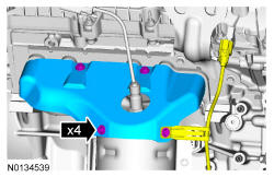
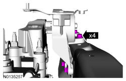
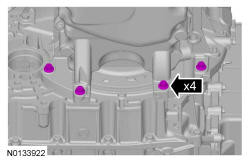
- 14.
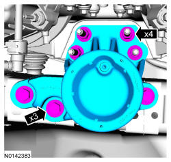
Install the RH catalytic converter heat shield, Catalyst Monitor Sensor (CMS) wiring harness bracket and the 4 bolts.- Tighten to 10 Nm (89 lb-in).
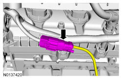
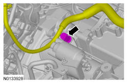
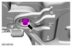
- 19.
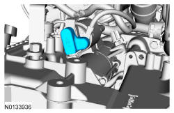
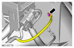
Position the wiring harness and attach the 3 wiring harness retainer to the valve cover stud bolt.

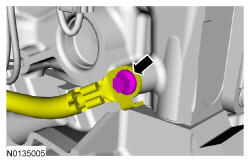
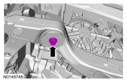
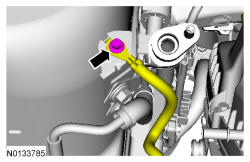
- 23.
Install the ground wire to the RH cylinder head and install the bolt.- Tighten to 10 Nm (89 lb-In).
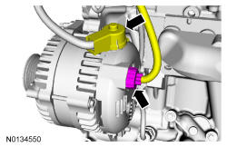
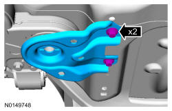
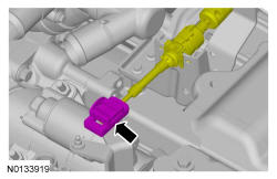
- 26.
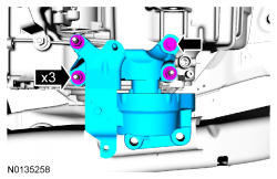
Attach the starter wire terminals and install the 2 nuts.- Tighten the B+ terminal nut to 12 Nm (106 lb-in).
- Tighten the S-terminal nut to 5 Nm (44 lb-in).

- 31.
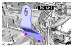
Install the engine mount, the 3 bolts and the 4 engine mount nuts hand tight.- Tighten the 3 engine mount bolts to 90 Nm (66 lb-ft).
- Tighten the 4 engine mount nuts to 63 Nm (46 lb-ft).
- 32.
Install the transaxle support insulator assembly the 3 nuts and the bolt.- Tighten the nuts to 63 Nm (46 lb-ft).
- Tighten the bolt to 80 Nm (59 lb-ft).
- 33.
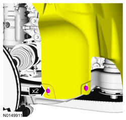
Install the 4 transmission support insulator-to-frame rail bolts.- Tighten the 2 bottom bolts to 55 Nm (41 lb-ft).
- Tighten the 2 top bolts to 70 Nm (52 lb-ft).
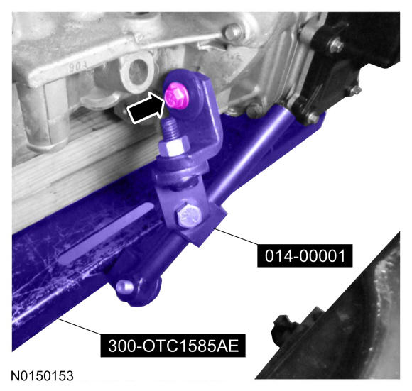
- 34.
Align the subframe and install the new front subframe bolts.- Tighten to 200 Nm (148 lb-ft).
NOTE:
RH shown, LH similar.
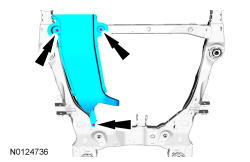
- 35.
Install the rear subframe brackets and the new subframe bracket-to-body bolts.- Finger tight at this stage.
NOTE:
RH shown, LH similar.
- 36.
Install the new subframe bracket bolts.- Tighten to 150 Nm (111 lb-ft).
NOTE:
RH shown, LH similar.
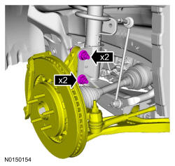
- 40.
Install the strut to the wheel knuckle and install the strut-to-wheel knuckle nuts and bolts.- Tighten to 250 Nm (184 lb-ft).
NOTE:
LH shown, RH similar.
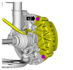
- 41.
Install the brake caliper and the guide pin bolts.- 432 mm (17 in) brakes: Tighten to 72 Nm (53 lb-ft).
- 457 mm (18 in) brakes: Tighten to 75 Nm (55 lb-ft).
NOTE:
LH shown, RH similar.
- 42.
Using the previously removed wheel hub nut, seat the LH and RH halfshafts.- Tighten to 350 Nm (258 lb-ft).
- Remove and discard the wheel hub nuts.
NOTE:
Apply the brake to keep the halfshaft from rotating.
NOTE:
LH shown, RH similar.
NOTE:
Do not tighten the wheel hub nut with the vehicle on the ground. The nut must be tightened to specification before the vehicle is lowered onto the wheels. Wheel bearing damage will occur if the wheel bearing is loaded with the weight of the vehicle applied.
- 43.
Install a new wheel hub nuts.- Tighten to 350 Nm (258 lb-ft).
NOTE:
Apply the brake to keep the halfshaft from rotating.
NOTE:
LH shown, RH similar.
NOTE:
The wheel hub nut contains a one time locking chemical that is activated by the heat created when it is tightened. Install and tighten the new wheel hub nut to specification within 5 minutes of starting it on the threads. Always install a new wheel hub nut after loosening or when not tightened within the specified time or damage to the components can occur.
- 44.
Install the new upper stabilizer link nut.- Tighten to 150 Nm (111 lb-ft).
NOTE:
LH shown, RH similar.
- 45.
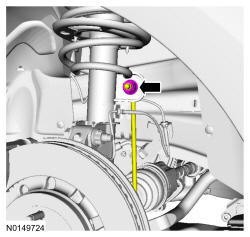
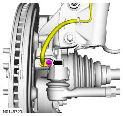
Install the wheel speed sensor and the bolt.- Tighten to 15 Nm (133 lb-in).
NOTE:
LH shown, RH similar.
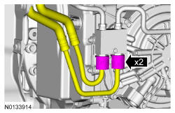
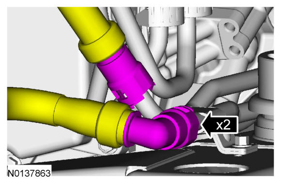
- 49.
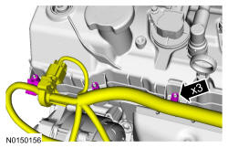
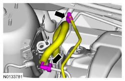
If equipped, connect the 2 PTU cooler hoses. For additional information, REFER to Fuel System General Information .
- 51.
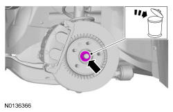
Install 3 new torque converter bolts by rotating the crankshaft clockwise.- Tighten to 55 Nm (41 lb-ft).
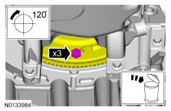
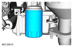
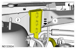
- 53.
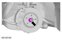
Install a new engine oil filter.- Tighten to 5 Nm (44 lb-in) and then rotate an additional 180 degrees.
NOTE:
Do not lubricate the engine oil filter gasket.
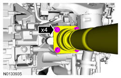
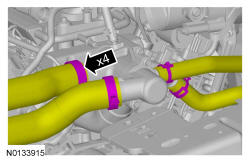
- 54.
Line up the index marks on the rear driveshaft to the index marks on the PTU flange made during removal and install the 4 new bolts.- Tighten to 70 Nm (52 lb-ft).
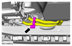
- 55.
Install the exhaust Y-pipe. For additional information, REFER to Exhaust System .
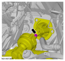
- 56.
Align and connect the steering column shaft to the steering gear and install the bolt.- Tighten to 20 Nm (177 lb-in).
NOTE:
Do not allow the intermediate shaft to rotate while it is disconnected from the gear or damage to the clockspring may occur. If there is evidence that the intermediate shaft has rotated, the clockspring must be removed and recentered. For additional information, REFER to Supplemental Restraint System
.
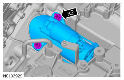
- 61.
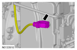
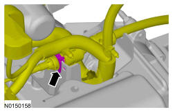
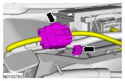
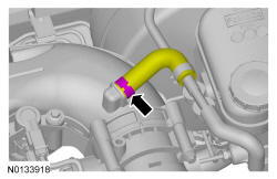
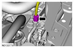
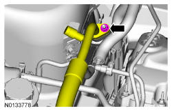
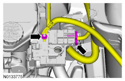
Connect the upper radiator hose, lower radiator hose and 2 heater hoses to the thermostat housing.
- 63.
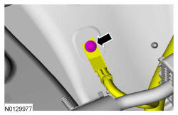
Install the engine wiring harness retainer to the bulkhead.- Slide the wiring harness in the bulkhead.
- Make sure the wiring harness retainer tab is below the bulkhead lip.
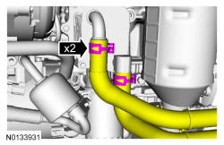
- 66.
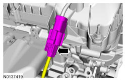
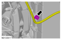
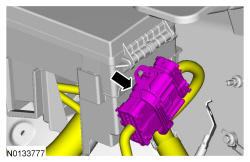
Connect the EVAP tube and the fuel supply tube quick connect coupling. REFER to Fuel System General Information .

- 69.
Install the degas bottle. REFER to Engine Cooling .
- 70.
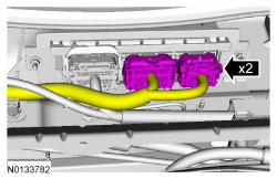
Using a new O-ring seal and gasket seal, install the A/C tube and the nut.- Tighten to 15 Nm (133 lb-in).
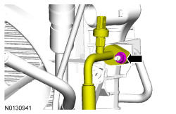
- 72.
Using a new O-ring seal and gasket seal, connect the A/C tube and install the nut.- Tighten to 15 Nm (133 lb-in).
- 73.
Install the accessory drive belt. REFER to Accessory Drive .
- 74.
Install the 2 RH and 2 LH lower pin-type retainers for the engine splash shields.
NOTE:
RH shown, LH similar.
- 75.
Install the front wheels and tires. REFER to Wheels and Tires .
- 79.
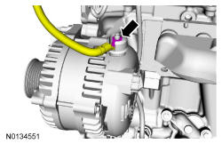
Connect the 2 battery feed cables to the positive battery terminal and install the nut.- Tighten to 5 Nm (44 lb-in).
- 80.
Install the battery tray. REFER to Battery, Mounting and Cables .
- 81.
Install the engine ACL and ACL outlet pipe. REFER to Intake Air Distribution and Filtering .
- 82.
Install the cowl panel. REFER to Front End Body Panels .
- 84.
Fill and bleed the cooling system. REFER to Engine Cooling .
- 85.
Recharge the A/C system. REFER to Climate Control DATC .