Oil Pan: Installation
- 1.
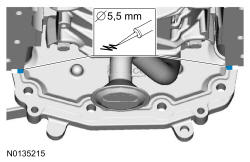
Apply a 5.5 mm (0.22 in) bead of Motorcraft ® High Performance Engine RTV Silicone to the 2 engine front cover-to-cylinder block joint areas on the sealing surface of the oil pan.
- 2.
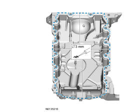
Apply a 3 mm (0.12 in) bead of Motorcraft ® High Performance Engine RTV Silicone to the sealing surface of the oil pan-to-engine block and to the oil pan-to-engine front cover mating surface.
NOTE:
The oil pan and the 4 specified bolts must be installed and the oil pan aligned to the cylinder block within 4 minutes of sealant application. Final tightening of the oil pan bolts must be carried out within 60 minutes of sealant application.
NOTE:
Failure to use Motorcraft ® High Performance Engine RTV Silicone may cause the engine oil to foam excessively and result in serious engine damage.
- 3.
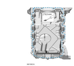
Apply a 5.5 mm (0.2165 in) bead of Motorcraft ® High Performance Engine RTV Silicone to the 2 crankshaft seal retainer plate-to-cylinder block joint areas on the sealing surface of the oil pan.
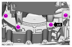
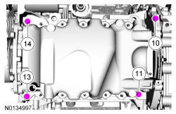
- 4.
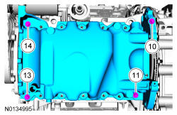
Install the oil pan and bolts 10, 11, 13 and 14 finger tight.
NOTE:
Keep the oil pan as close as possible to the transmission while installing, then slide forward towards the engine front cover to prevent wiping off of the sealant.
NOTE:
The oil pan and the 4 specified bolts must be installed within 4 minutes of sealant application.
- 5.
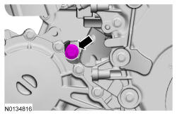
Draw the bellhousing up to the engine by tightening the LH bellhousing-to-engine bolt. Do not torque at this time.
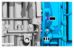
- 6.
Draw the bellhousing up to the engine by tightening the RH bellhousing-to-engine bolt. Do not torque at this time.
NOTE:
AWD vehicle shown, FWD similar. Parts removed from graphic for clarity.
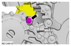
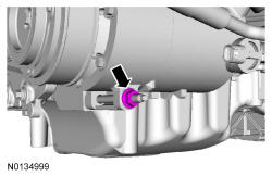
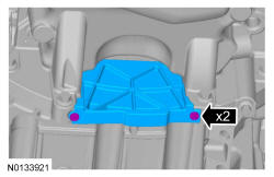
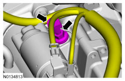
- 8.
Install the A/C compressor nut and stud.- Tighten the stud to 9 Nm (80 lb-in).
- Hand tighten the nut.
NOTE:
It may be necessary to roll the bottom of the engine back for the A/C compressor stud to clear the subframe.
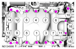
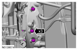
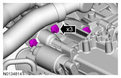
- 11.
Install the remaining oil pan bolts and tighten in the sequence shown.- Tighten bolts 1 through 9 and 11 through 14 to 20 Nm (177 lb-in), then rotate and additional 45 degrees.
- Tighten bolts 15 and 16 to 10 Nm (89 lb-in), then rotate and additional 45 degrees.
- Tighten bolt 10 to 20 Nm (177 lb-in), then rotate and additional 45 degrees.
- 15.
Tighten the RH bellhousing-to-engine bolt.- Tighten to 48 Nm (35 lb-ft).
NOTE:
AWD vehicle shown, FWD similar. Parts removed from graphic for clarity.
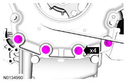
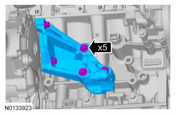
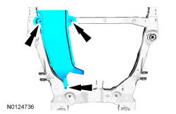
- 18.
If equipped with AWD, install the 5 PTU support bracket bolts and the PTU support bracket.- Tighten to 70 Nm (52 lb-ft).
- 19.
If equipped with AWD, install the catalytic converter - RH manifold. REFER to Exhaust System .
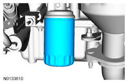
- 20.
Install a new engine oil filter.- Tighten to 5 Nm (44 lb-in) and then rotate an additional 180 degrees.
NOTE:
Do not lubricate the engine oil filter gasket.
- 21.
Install the transaxle support insulator - anti-roll. For FWD vehicles, REFER to Automatic Transmission 6F50 6F55 or for AWD vehicles, REFER to Automatic Transmission 6F50 6F55 .
- 22.
Install the exhaust Y-pipe. REFER to Exhaust System .
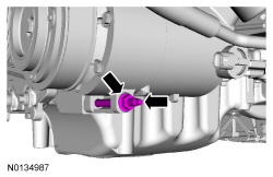
- 25.
Install the starter stud bolt and attach the wire harness retainer to the starter stud bolt.- Tighten to 27 Nm (20 lb-ft).
- 27.
Install the battery tray. REFER to Battery, Mounting and Cables .
- 28.
Install the ACL tray assembly and ACL outlet pipe. REFER to Intake Air Distribution and Filtering .