Removal And Installation: Engine: Removal
WARNING: This page is about a different variant/trim than selected.
- 1.
With the vehicle in NEUTRAL, position it on a hoist. REFER to Jacking and Lifting .
- 2.
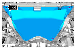
Remove the cowl panel. REFER to Front End Body Panels .
- 3.
Release the fuel system pressure. REFER to Fuel System General Information .
- 4.
Remove the engine ACL and ACL outlet pipe. REFER to Intake Air Distribution and Filtering .
- 5.
Remove the battery tray. REFER to Battery, Mounting and Cables .
- 6.
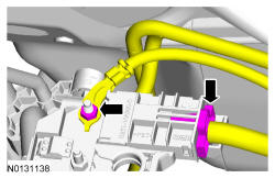
Disconnect the engine wiring harness electrical connector.- Remove the stud bolt and the ground wire.
- 7.
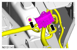
Disconnect the power feed electrical connector from the positive battery terminal.- Remove the nut and disconnect the power feed wire from the positive battery terminal.
- 8.
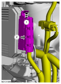
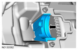
Disconnect the TCM electrical connector.- 1.
Lift the locking clip up.
- 2.
Slide the electrical connector straight out of the TCM.
- 1.
NOTE:
Keep the TCM electrical connector straight when disconnecting it or damage to the connector terminals can occur.
- 14.
Drain the engine cooling system. REFER to Engine Cooling .
- 15.
Remove the degas bottle. REFER to Engine Cooling .
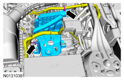
- 16.
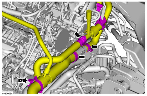
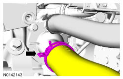
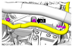
Loosen the 2 clamps and disconnect the upper radiator hose and the heater hose.- Disconnect the heater hose quick connect coupling.
- Detach the hoses from the 2 retaining clips.
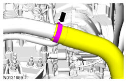
- 18.
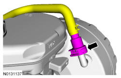
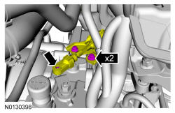
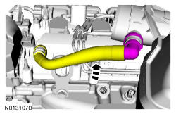
Disconnect the vacuum tube quick connect coupling from the brake booster. REFER to Fuel System General Information , Disconnect - Type 1.
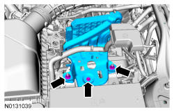
- 19.
Disconnect the selector lever cable end from the manual control lever, remove the 2 bracket bolts and position the selector lever cable and bracket aside.
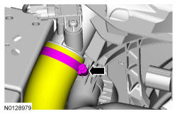
- 20.
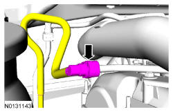
Disconnect the fuel supply tube. REFER to Fuel System General Information , Disconnect - Type 2.
- 21.
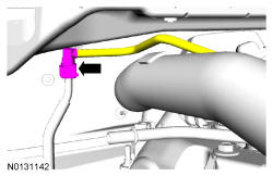
Disconnect the EVAP tube. REFER to Fuel System General Information , Disconnect - Type 2.
- 22.
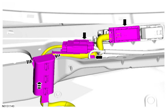
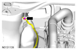
Disconnect the wiring harness electrical connector and the PCM electrical connector.- Detach the wiring harness retainer.
- Push the wiring harness retainer tabs in and slide the wiring harness up and out of the bulkhead.
- 25.
Remove the catalytic converter. REFER to Exhaust System .
- 26.
Remove the front subframe. REFER to Uni-Body, Subframe and Mounting System . Position the stabilizer bar aside and support with a length of mechanics wire.
- 27.
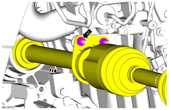
Remove the 2 nuts and slide the RH halfshaft assembly out of the transaxle.- Position the halfshaft aside and support with a length of mechanics wire.
- 28.
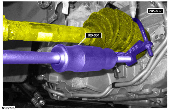
Using 205-832 and 100-001 T50T-100-A, separate the halfshaft from the transaxle.- Position the halfshaft aside and support with a length of mechanics wire.
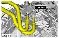
- 33.
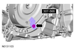
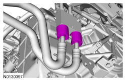
Using 307-569, disconnect the transaxle fluid cooler tubes from the transaxle fluid cooler thermal bypass valve.
- 34.
Remove the A/C drive belt. REFER to Accessory Drive .
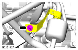
- 35.
Disconnect the 2 A/C compressor electrical connectors.- Detach the wiring harness retainer from the A/C tube stud bolt.
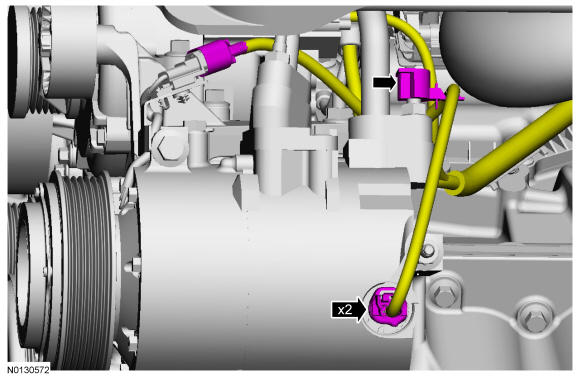
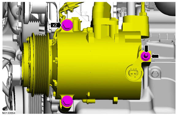
- 37.
Remove the A/C compressor nut, stud and the 2 bolts.- Position the A/C compressor aside and support with a length of mechanics wire.
- 40.
Remove the transaxle support insulator bolt.- Lower the engine and transaxle from the engine compartment.
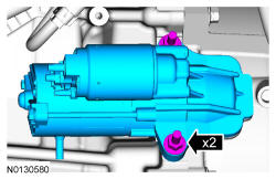
- 41.
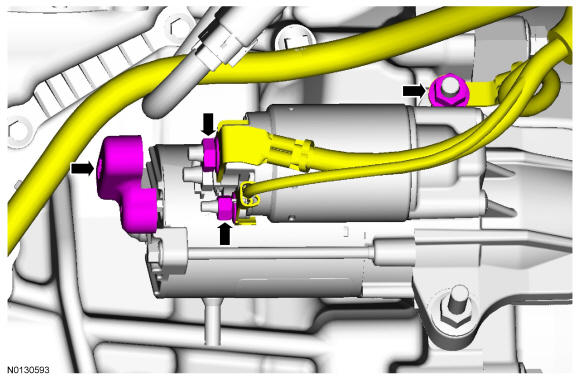
Remove the starter cable cover and the 2 nuts.- Detach the 2 wire terminals from the starter.
- Remove the nut and the ground wire from the starter stud bolt.
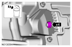
- 44.
Remove and discard the 4 torque converter nuts.
NOTE:
Mark one stud and the flexplate for assembly reference.
NOTE:
Only rotate the engine in a clockwise direction or engine damage will occur.

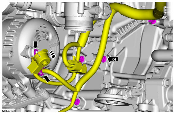
- 46.
Position the generator cap aside and remove the nut and wire terminal.- Disconnect the wire harness electrical connector.
- Detach the 4 wiring harness retainers from the engine.
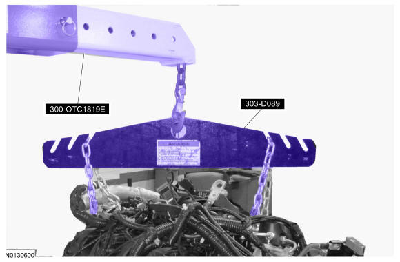
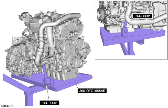
- 48.
Using the 300-OTC1819E and 303-D089 D93P-6001-A3 remove the engine and transaxle from the 300-OTC1585AE.