Removal And Installation: Engine: Installation
WARNING: This page is about a different variant/trim than selected.
- 2.
Using the 300-OTC1819E and 303-D089 D93P-6001-A3, assemble the engine and transaxle.
NOTE:
Align the torque converter stud marked during removal with the mark on the flexplate.
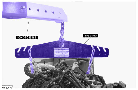
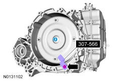
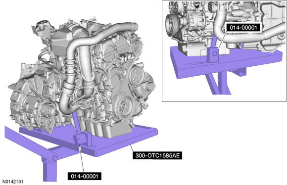
- 6.
Using the 300-OTC1819E and 303-D089 D93P-6001-A3 position the engine and transaxle onto the 300-OTC1585AE.
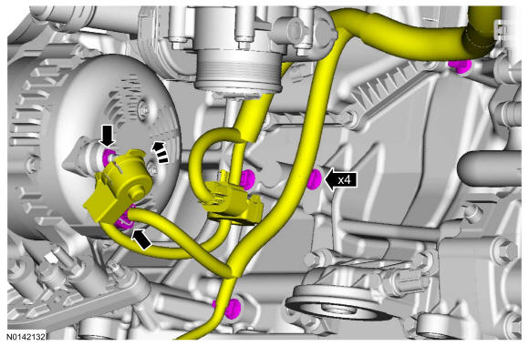
- 9.
Install the wire terminal and nut on the generator.- Tighten to 17 Nm (150 lb-in) and install the cap.
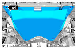
- Disconnect the wire harness electrical connector.
- Attach the 4 wiring harness retainers to the engine.

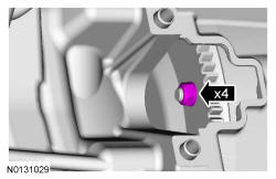
- 11.
Install the 4 torque converter nuts.- Tighten to 40 Nm (30 lb-ft).
NOTE:
Only rotate the engine in a clockwise direction or engine damage will occur.
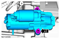
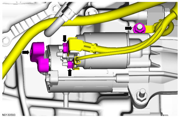
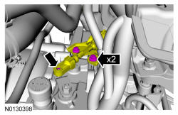
- 14.
Install the 2 starter wire terminals, the ground wire and the 3 nuts.- Tighten the ground wire nut to 18 Nm (159 lb-in).
- Tighten the large starter wire terminal nut to 12 Nm (106 lb-in).
- Tighten the small starter wire terminal nut to 5 Nm (44 lb-in).
- Install the starter cable cover.
- 15.
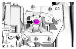
Raise the engine and transaxle assembly into the vehicle and install the transaxle support insulator bolt.- Tighten to 150 Nm (111 lb-ft).
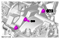
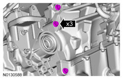
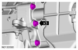
- 16.
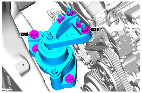
Install the engine support insulator, the 4 nuts and the 3 bolts.- Tighten bolts to 90 Nm (66 lb-ft).
- Tighten nuts to 125 Nm (92 lb-ft).
- 17.
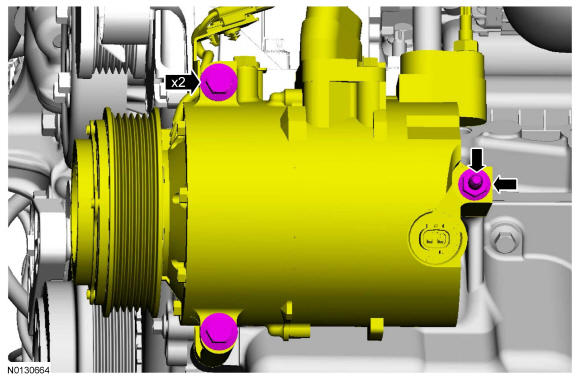
Install the A/C compressor, the 2 bolts and the stud.- Tighten the bolts to 25 Nm (18 lb-ft) and the stud to 9 Nm (80 lb-in).
- Install the nut and tighten to 25 Nm (18 lb-ft).
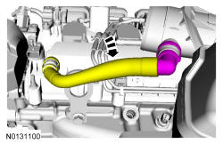
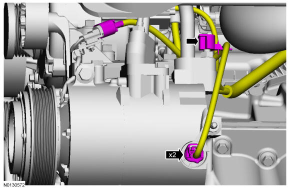
- 19.
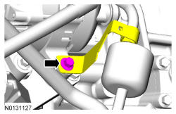
Connect the 2 A/C compressor electrical connectors.- Attach the wiring harness retainer to the A/C tube stud bolt.
- 20.
Install the A/C drive belt. REFER to Accessory Drive .
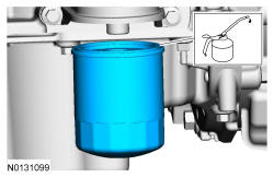
- 24.
Install a new engine oil filter.- Tighten to 8 Nm (71 lb-in) plus an additional 180 degrees.
NOTE:
Lubricate the engine oil filter gasket with clean engine oil prior to installing the oil filter.
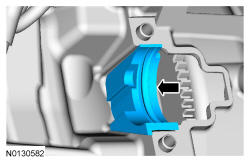
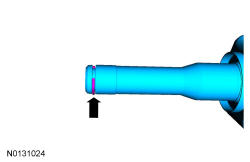
- 25.
Install a new circlip.
NOTE:
Make sure to install the correct circlip for this application. Failure to use the correct diameter circlip may result in shaft removal concerns or shaft damage during vehicle operation.

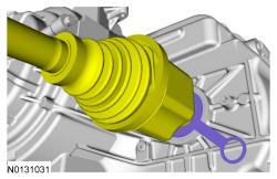
- 27.
Push the LH halfshaft into the transmission so the circlip locks into the differential side gear. Pull the halfshaft inner end to make sure the circlip is locked.
NOTE:
The sharp edges on the halfshaft splines can slice or puncture the oil seal. Use care when inserting the halfshaft into the transmission or damage to the seal may occur.
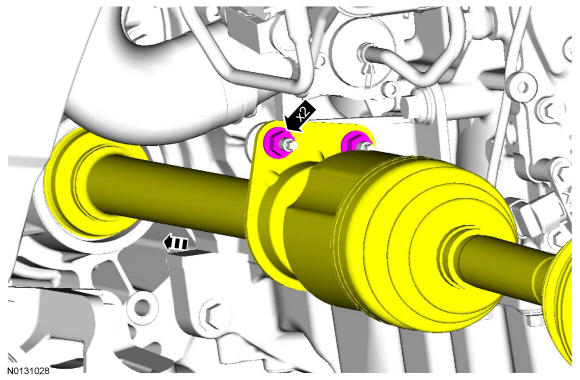
- 28.
Install the RH halfshaft in the transmission and engage the halfshaft splines with the transmission side gears and install the 2 halfshaft nuts.- Torque: 25 Nm (18 lb-ft).
- 29.
Install the subframe. REFER to Uni-Body, Subframe and Mounting System .
- 30.
Install the catalytic converter. REFER to Exhaust System .
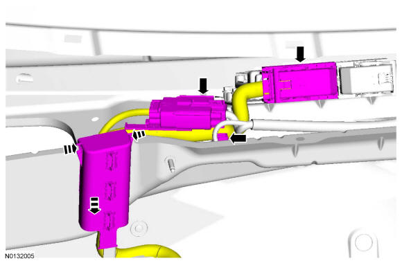
- 33.
Connect the wiring harness electrical connector and the PCM electrical connector.- Slide the wiring harness down onto the bulkhead until the retainer tabs engage.
- Attach the wiring harness retainer.
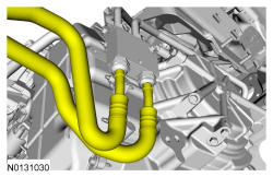
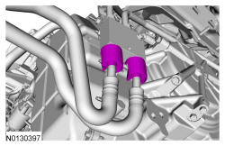
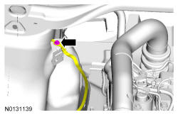
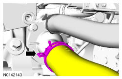
- 34.
Connect the EVAP tube. REFER to Fuel System General Information , Connect - Type 2.
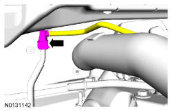
- 35.
Connect the fuel supply tube. REFER to Fuel System General Information , Connect - Type 2.
- 36.
Connect the transaxle selector lever cable end to the manual control lever and install the 2 bracket bolts.- Tighten to 25 Nm (18 lb-ft).
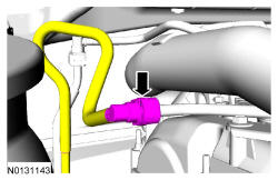
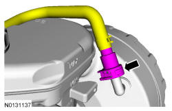
- 37.
Connect the vacuum tube quick connect coupling to the brake booster. REFER to Fuel System General Information , Connect - Type 1.
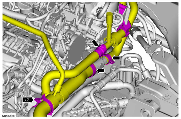
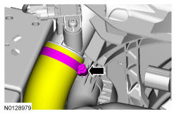
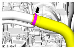
- 39.
Install the upper radiator hose, the heater hose and the 2 clamps.- Connect the heater hose quick connect coupling.
- Attach the hoses to the 2 retaining clips.
- 40.
Install the degas bottle. REFER to Engine Cooling .
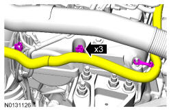
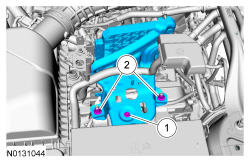
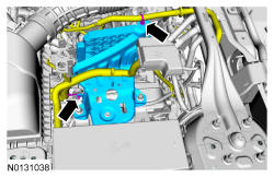
- 44.
Install the TCM bracket, install the 2 nuts and install the bolt.- 1.
Tighten to 11 Nm (97 lb-in).
- 2.
Tighten to 63 Nm (46 lb-ft).
- 1.
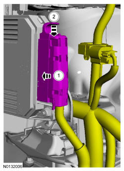
- 46.
Connect the TCM electrical connector.- 1.
Slide the electrical connector straight into the TCM.
- 2.
Push the locking clip down.
- 1.
NOTE:
Keep the TCM electrical connector straight when connecting it or damage to the connector terminals can occur.
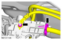
- 47.
Connect the power feed wire to the positive battery terminal and install the nut.- Tighten to 9 Nm (80 lb-in).
- Connect the power feed electrical connector to the positive battery terminal.
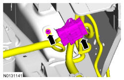
- 48.
Install the ground wire and stud bolt.- Tighten to 10 Nm (89 lb-in).
- Connect the engine wiring harness electrical connector.
- 49.
Install the battery tray. REFER to Battery, Mounting and Cables .
- 50.
Install the engine ACL and ACL outlet pipe. REFER to Intake Air Distribution and Filtering .
- 51.
Install the cowl panel. REFER to Front End Body Panels .
- 53.
Fill and bleed the engine cooling system. REFER to Engine Cooling .