Valve Cover: Installation
WARNING: This page is about a different variant/trim than selected.
- 1.
Clean and inspect the sealing surfaces.
NOTE:
Do not use metal scrapers, wire brushes, power abrasive discs or other abrasive means to clean the sealing surfaces. These tools cause scratches and gouges which make leak paths.
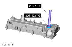
- 2.
Using the 205-153 T80T-4000-W and 303-1247/2, install new VCT solenoid seals.
NOTE:
Installation of new seals is only required if damaged seals were removed during disassembly of the engine.
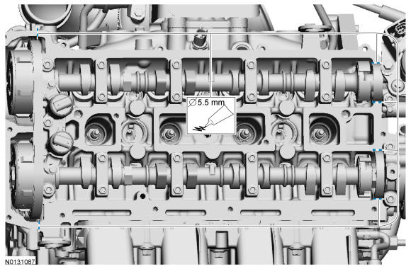
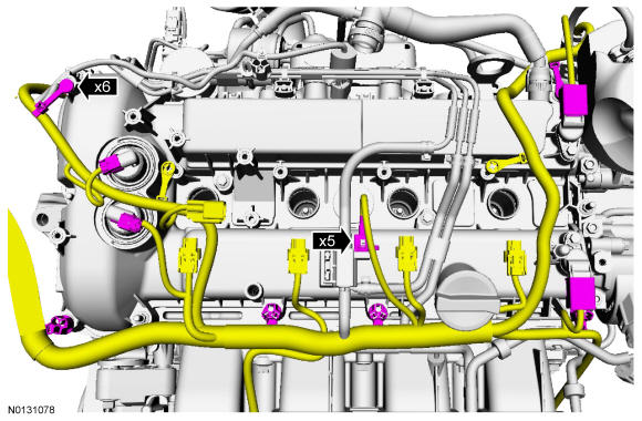
- 3.
Apply a 5.5 mm (0.216 in) drop of Silicone Gasket and Sealant to the 6 locations shown.
NOTE:
The valve cover must be secured within 10 minutes of sealant application. If the valve cover is not secured within 10 minutes, the sealant must be removed and the sealing area cleaned with metal surface prep.
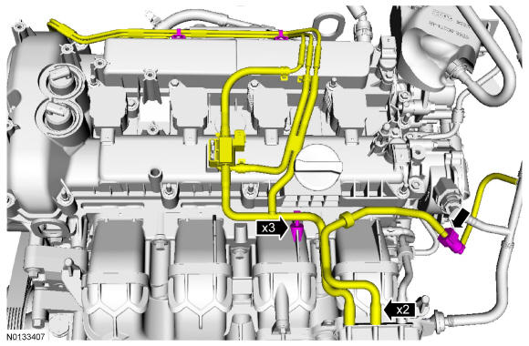
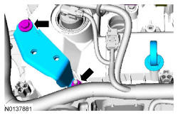
- 5.
Connect the 2 vacuum hoses to the vacuum reservoir.- Connect the vacuum tube quick connect coupling. REFER to Fuel System General Information .
- Attach the 3 vacuum hose retainers.
- 8.
Install the CAC intermediate tube mounting bracket, the nut and the bolt.- Tighten to 8 Nm (71 lb-in).
- Install the oil level indicator.
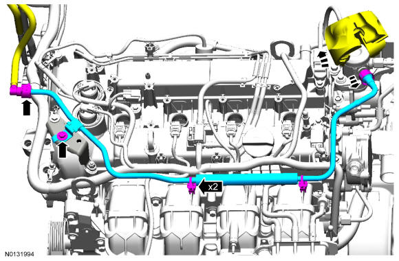
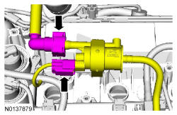
- 9.
Connect the fuel supply tube from the fuel jumper tube and the fuel jumper tube from the fuel injection pump. REFER to Fuel System General Information .- Attach the 2 fuel tube retainers to the intake manifold.
- Install the fuel jumper tube bolt.
- Tighten to 8 Nm (71 lb-in).
- 10.
Install the coil-on-plug assemblies. Refer to IGNITION COIL-ON-PLUG .
- 11.
Install the ACL outlet pipe, the turbocharger inlet pipe and the CAC inlet/intermediate inlet tube assembly. REFER to Intake Air Distribution and Filtering .
- 13.
Connect the EVAP canister purge valve electrical connector and vapor tube. REFER to Fuel System General Information .
- 14.
Connect the battery ground cable. REFER to Battery, Mounting and Cables .