Battery Cables - 3.5L Ti-VCT: Removal
WARNING:
Before beginning any service procedure in this service information, refer to SAFETY WARNINGS
- 1.
With the vehicle in NEUTRAL, position it on a hoist. REFER to Jacking and Lifting , Lifting Points.
- 2.
Disconnect the battery. Refer to Battery Disconnect .
- 3.
Remove the ACL tray assembly and outlet pipe. REFER to Intake Air Distribution and Filtering .
- 4.
Remove the BJB terminal nut and position the cable aside.- 1.
To install, tighten to 9 Nm (80 lb-in).
- 1.
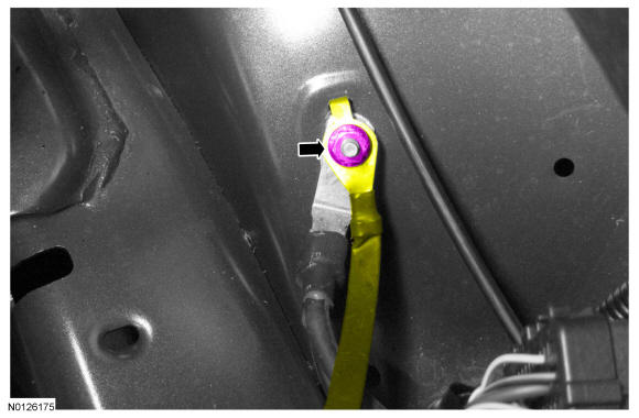
- 7.NOTE: Battery removed to show clarity.
Remove the battery cable body ground terminal stud nut and position the ground strap aside.
- 1.
To install, tighten to 10 Nm (89 lb-in).
- 1.
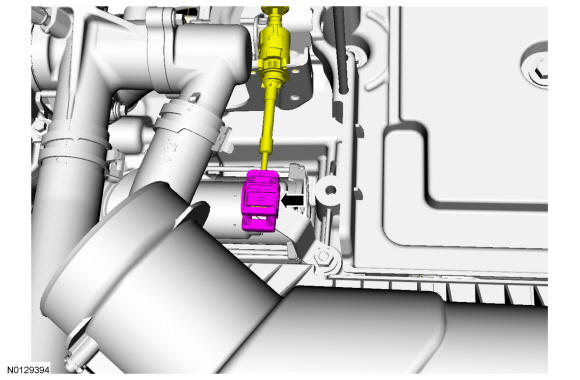
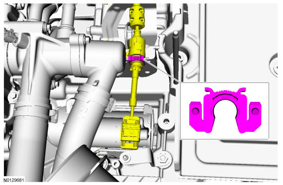
- 10.NOTE: To prevent selector lever cable damage, do not apply force to the selector lever cable between the manual control lever and the selector lever cable bracket.NOTE: When installing the selector lever cable, make sure that the selector lever cable locking tabs are locked in place. Press the selector lever cable into the selector lever cable bracket and listen for the selector lever cable retainer to click in place. Pull back on the selector lever cable to make sure that the selector lever is locked into the selector lever cable bracket.
Disconnect the selector lever cable end from the manual control lever.
- 13.
Remove the starter solenoid wire terminal nut and position the cable aside.- 1.
To install, tighten to 5 Nm (44 lb-in).
- 1.
- 14.
Remove the starter solenoid positive cable terminal nut and position the cable aside.- 1.
To install, tighten to 12 Nm (106 lb-in).
- 1.
- 15.
Remove the battery cable engine ground terminal bolt and position the cable aside.- 1.
To install, tighten to 15 Nm (133 lb-in).
- 1.
- 17.
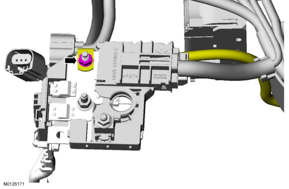
Position the generator B+ cable terminal cover aside, remove the nut and position the generator B+ cable terminal aside.- 1.
To install, tighten to 17 Nm (150 lb-in).
- 1.
- 19.
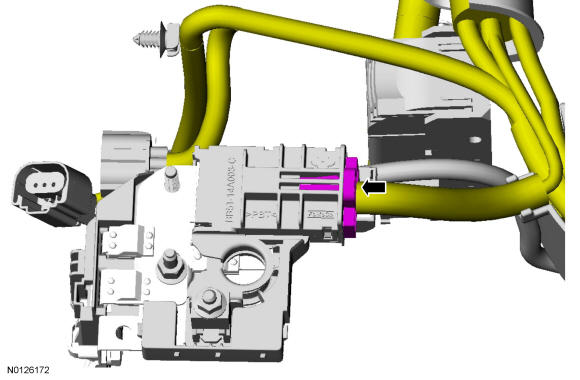
Disconnect the 3 wire harness retainers from the transmission stud bolts and the selector lever cable bracket.
- 23.
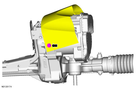
Remove the flap heat shield bolt and position the flap heat shield to access the PSCM electrical connectors.- 1.
To install, tighten to 11 Nm (97 lb-in).
- 1.