Removal And Installation: Installation
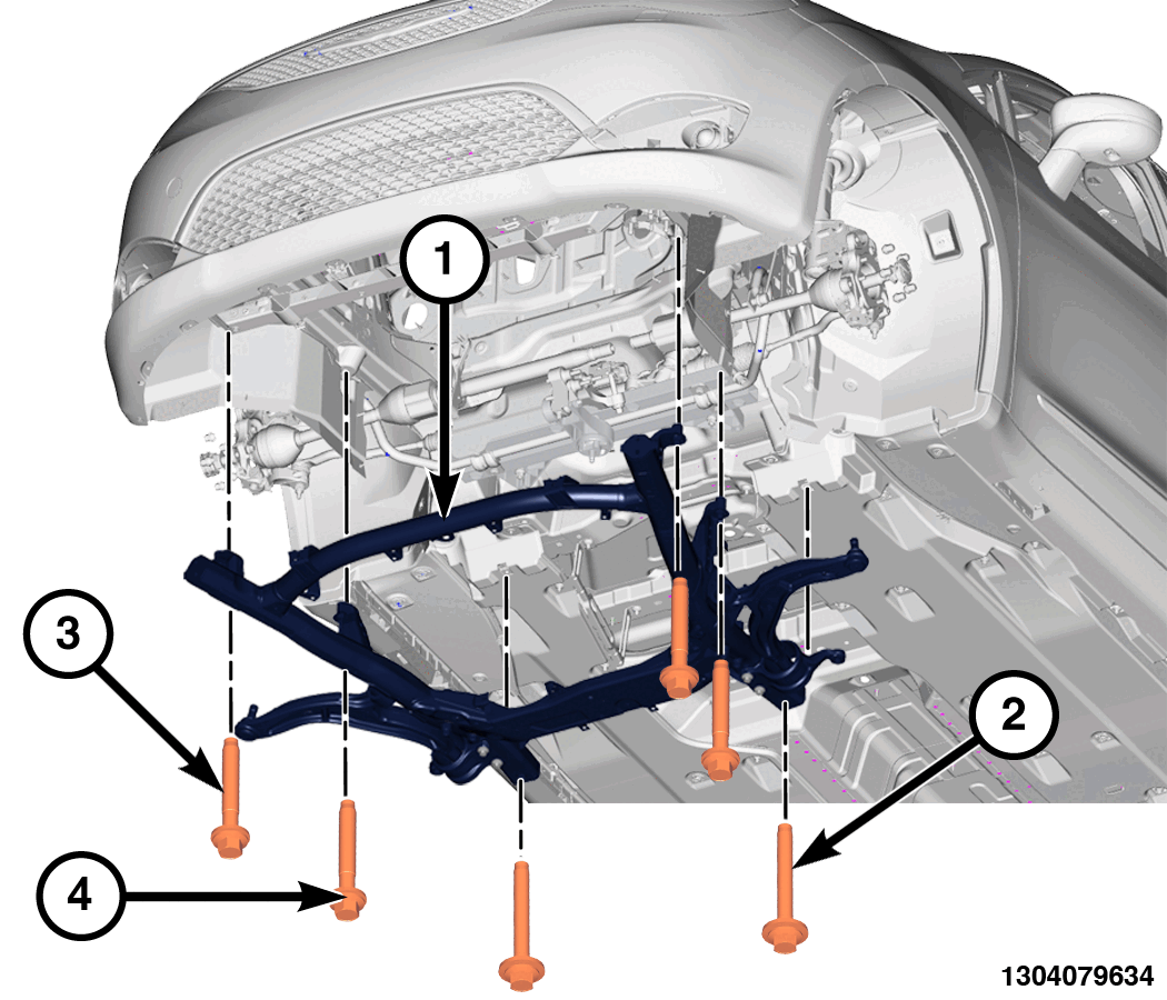
- Using a suitable lifting device, install the crossmember and install the NEW
front and mid position bolts (3).
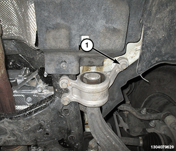
- Install the rear control arm mount outer bolts (1).
- Using the marks made previously during removal, line up the crossmember with the rear marks (1).
- Using the marks made previously during removal, line up the crossmember with the front marks (1).
- Tighten the rear bolts (2) to the proper torque specification. Refer to TECHNICAL SPECIFICATIONS .
- Tighten the NEW
front four bolts (3) to the proper torque specification. Refer to TECHNICAL SPECIFICATIONS .
- Tighten the control arm mount bolts to the proper torque specification. Refer to FRONT, TECHNICAL SPECIFICATIONS
.
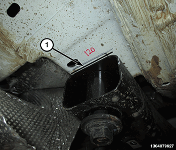
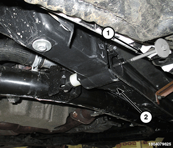
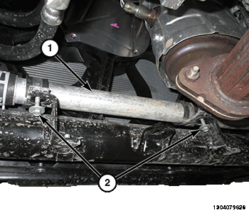
- Install the bolts (1) attaching the radiator support (2) to the crossmember and tighten to the proper torque specifications. Refer to TECHNICAL SPECIFICATIONS .
- Install the bolts (2) attaching the coolant pipe (1) to the crossmember and tighten to the proper torque specifications. Refer to TECHNICAL SPECIFICATIONS .
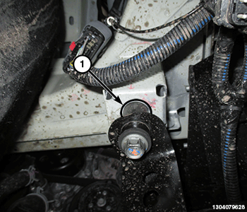
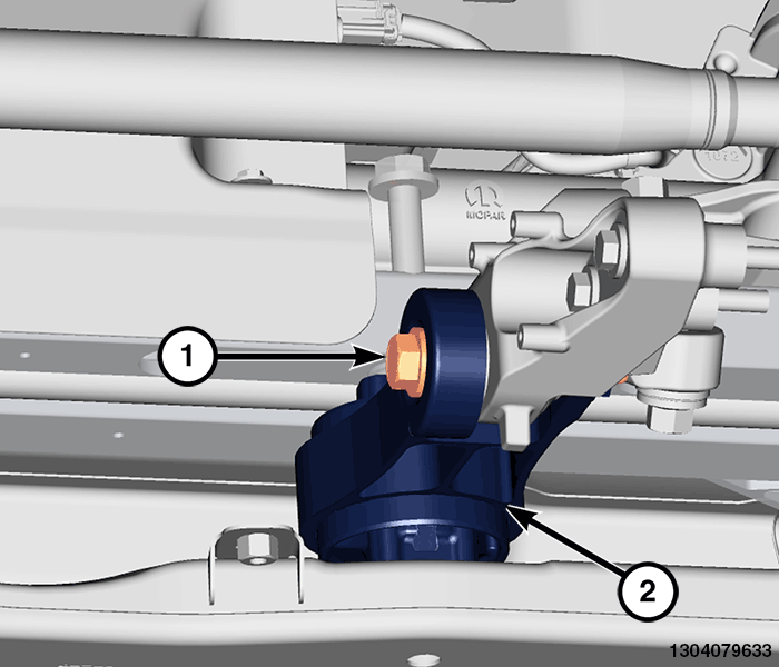
- Position the mount (2) back into place and install the bolt (1).
- Tighten the bolts (1) to the proper torque specification. Refer to TECHNICAL SPECIFICATIONS .
- Install the exhaust crossunder pipe. Refer to PIPE, EXHAUST CROSSUNDER, REMOVAL AND INSTALLATION .
- Install the side belly pans. Refer to BELLY PAN, SIDE, REMOVAL AND INSTALLATION .
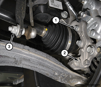
- Install the stabilizer bar link to the stabilizer bar and install the stabilizer bar link nut (3) and tighten to the proper torque specifications. Refer to FRONT, TECHNICAL SPECIFICATIONS .
- Install the axles shafts. Refer to REMOVAL AND INSTALLATION or REMOVAL AND INSTALLATION .
- Connect the outer tie rods and the lower ball joints to the steering knuckles. Refer to KNUCKLE, STEERING, REMOVAL AND INSTALLATION
.
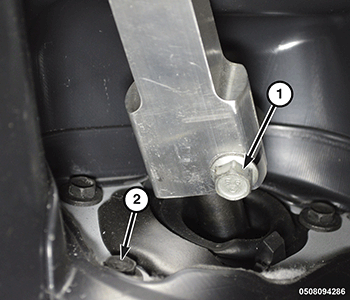
- Install the dash seal to dash panel bolts (2) and tighten to the proper torque specifications. Refer to TECHNICAL SPECIFICATIONS
.NOTE:
Apply medium strength threadlocker to the bolts.
- Install a NEW steering shaft to steering gear pinch bolt (1) and tighten to the proper torque specifications. Refer to TECHNICAL SPECIFICATIONS .
- Install tire and wheel assemblies. Refer to REMOVAL AND INSTALLATION .
- Connect the negative battery cable. If equipped with an Intelligent Battery Sensor (IBS), connect the IBS connector to the negative battery cable.
- Perform a wheel alignment. Refer to WHEEL ALIGNMENT, STANDARD PROCEDURE .
- Perform the Electric Power Steering (EPS) verification test. Refer to EPS VERIFICATION TEST .