Removal And Installation
REMOVAL
- Disconnect and isolate the negative battery cable. If equipped with an Intelligent Battery Sensor (IBS), disconnect the IBS connector first before disconnecting the negative battery cable.
- Raise and support the vehicle. Refer to HOISTING, STANDARD PROCEDURE
.
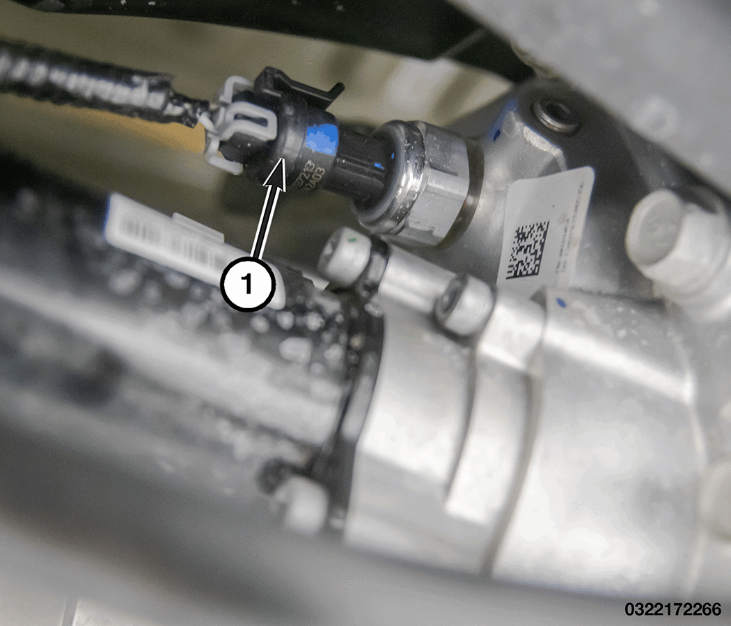
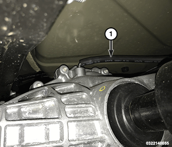
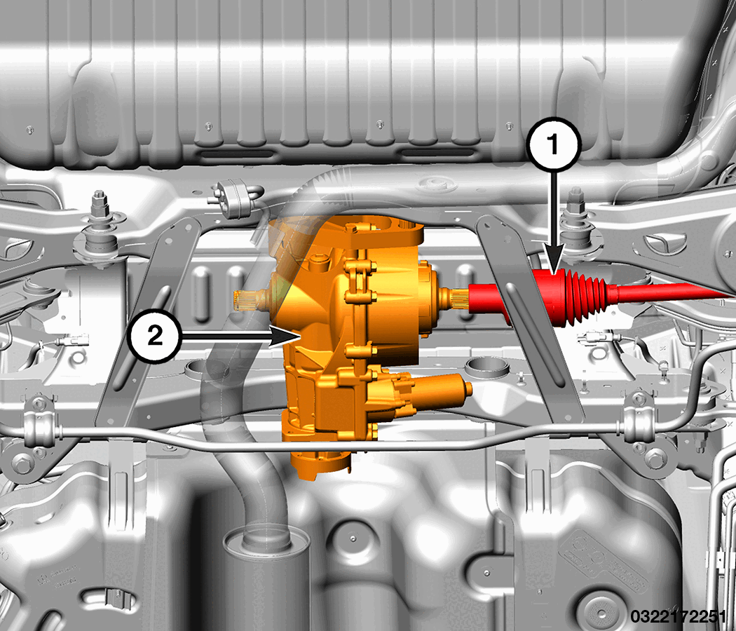
- Disconnect the pressure sensor wire harness connector (1).
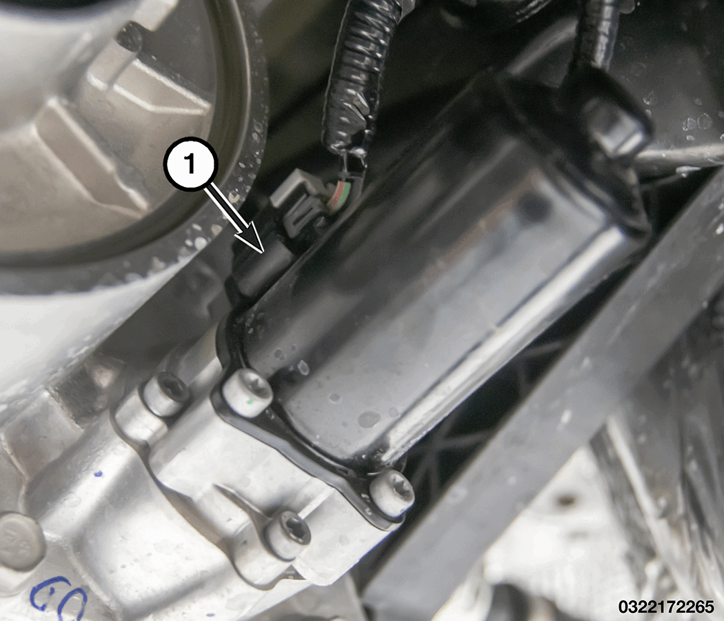
- Disconnect the pump motor wire harness connector (1).CAUTION:
Do not allow the propeller shaft to hang from the vehicle unsupported. Damage may occur to the joint, boot, and center bearing from over-angulation.
- Apply alignment index marks to the rear propeller shaft flange and the rear pinion flange.
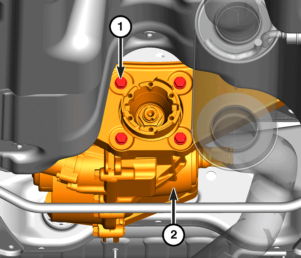
- Remove and discard the rear propeller shaft bolts (1).
- Separate the rear propeller shaft from the rear pinion flange and secure the shaft to the side.
- Remove the rear left halfshaft. Refer to REMOVAL AND INSTALLATION .
- Support the Rear Drive Module (RDM) with a suitable jack and secure it with chains.
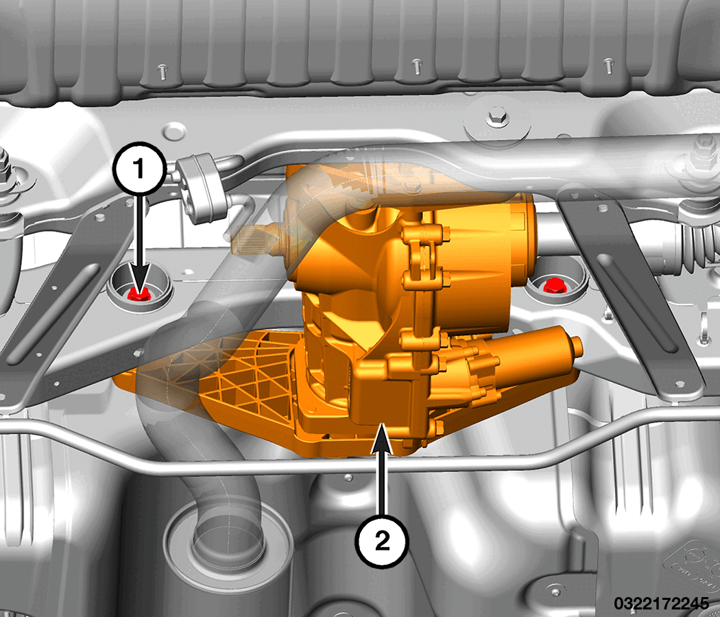
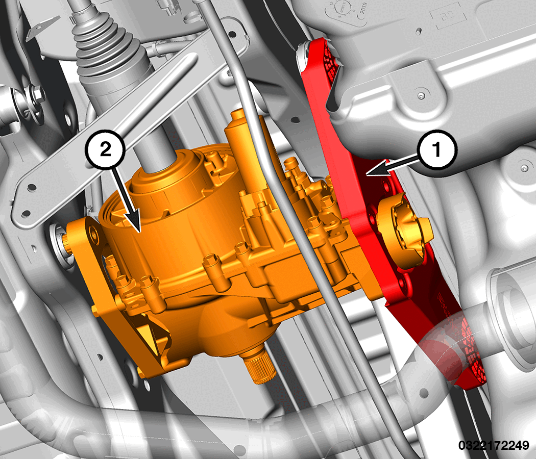
- Remove the front RDM bracket to isolator bolts (1).
- Remove the RDM bracket to RDM bolts (1).
- Remove the RDM bracket (1) from the vehicle.
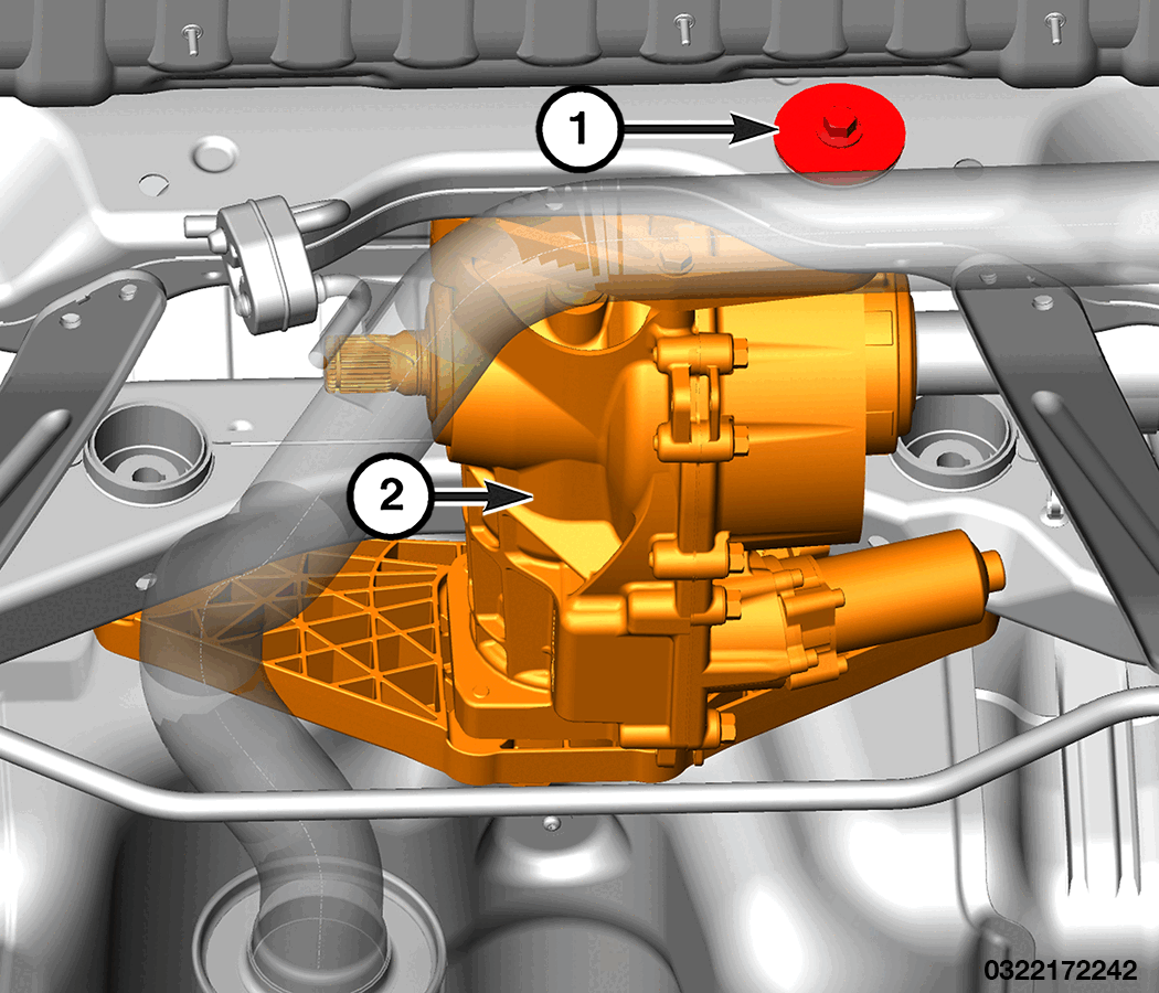
- Remove the rear RDM isolator bolt (1)
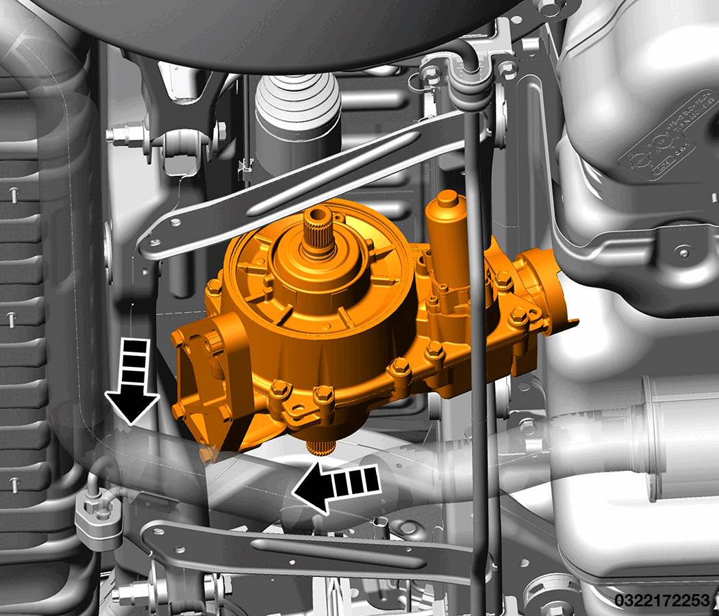
- Disconnect the vent hose (1).
- Disconnect the RH halfshaft (1) from the RDM (2).
- Remove the RDM from the vehicle.
INSTALLATION
- Secure the RDM on a suitable jack and secure it with chains.
- Position the RDM in the vehicle.
- Install the RH halfshaft on the RDM.
- Raise the RDM with the RH halfshaft into position.
- Connect the vent hose (1).
- Install rear RDM isolator bolt (1) hand tight.
- Place the RDM bracket (1) in the vehicle.
- Install the RDM bracket to RDM bolts (2) and tighten to the proper torque specifications. Refer to TECHNICAL SPECIFICATIONS .
- Install the front RDM bracket to isolator bolts (1) and tighten to the proper torque specifications. Refer to TECHNICAL SPECIFICATIONS .
- Tighten the rear RDM to isolator bolt (1) to the proper torque specifications. Refer to TECHNICAL SPECIFICATIONS .
- Install the rear left halfshaft Refer to REMOVAL AND INSTALLATION .
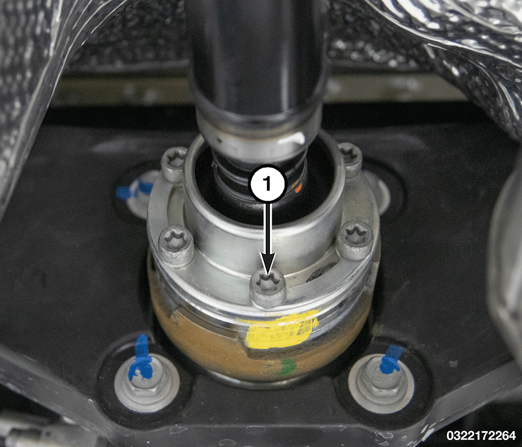
- Install the RH rear halfshaft hub nut (1) and tighten to the proper torque specifications. Refer to TORQUE SPECIFICATIONS
.NOTE:
The six bolts that are used to secure the propeller shaft to the RDM input flange MUST be replaced.
NOTE:Use of Anti-seize compound is prohibited.
- Connect the propeller shaft to the RDM, align the index marks made during removal, install NEW
rear propeller shaft bolts (1) and tighten to the proper torque specifications. Refer to TECHNICAL SPECIFICATIONS
.
- Connect the pump motor wire harness connector (1).
- Connect the pressure sensor wire harness connector (1).
- Fill the RDM with differential fluid. Refer to FLUID, DIFFERENTIAL, STANDARD PROCEDURE .
- Remove the support and lower the vehicle.
- Connect the negative battery cable. If equipped with an Intelligent Battery Sensor (IBS), connect the IBS connector.