Disassembly And Assembly: Disassembly
Remove the valve body from the transmission and place the valve body on a clean oil absorbent work surface. Refer to VALVE BODY, REMOVAL AND INSTALLATION .
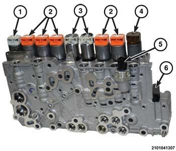
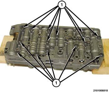
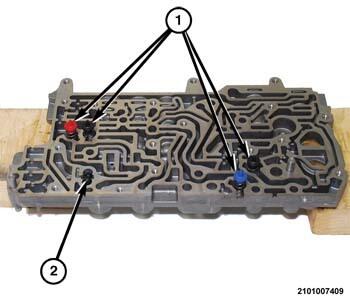
- Remove the solenoids (1 - 4) from the valve body.NOTE:
Each type of solenoid has a unique color end cover.
- 1 = System Pressure Regulator Solenoid
- 2 = Pressure Regulator Solenoids
- 3 = Dog Clutch Solenoids
- 4 = Parking Lock Solenoid
- Remove the pressure sensor from the valve body.
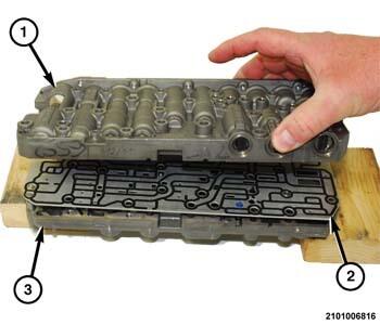
- Position the valve body on the wooden blocks with outer side up.
- Remove the screws (1) holding the valve body halves together.
- Separate the outer valve body (1) from the separator plate (2).
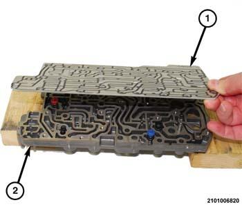
- Lift the separator plate (1) upward and off of the inner valve body (2).
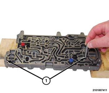
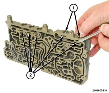
- Remove the guide pins (1) from the inner valve body.
- Remove the color coded check valves (1) from the inner valve body.
- Remove the toggling, connected check-balls (2) from the inner valve body.
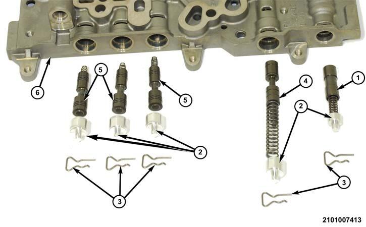
- Position the outer valve body on the work surface inside up to gain access to the valve retaining spring clips.NOTE:
DO NOT damage the filter screen during removal.
- Using a suitable prying tool, remove the filter screen (1) from the bore in the outer valve body (11).
- Remove the bullets (8), sleeves (7), and pressure regulator valves (6) from the bores in the outer valve body (11).
- Remove the parking lock valve (10) from the bore in the outer valve body (11).
- Using a suitable prying tool, remove the spring clips (12) holding the lubrication valve plugs in the bores in the outer valve body (11).
- Remove the plugs (5), lubrication valves and springs (3) from the bores in the outer valve body (11).
- Using a suitable prying tool, remove the spring clip (12) holding the MV park lock valve plug in the bore in the outer valve body (11).
- Remove the spring and MV park lock valve (9) from the bore in the outer valve body (11).
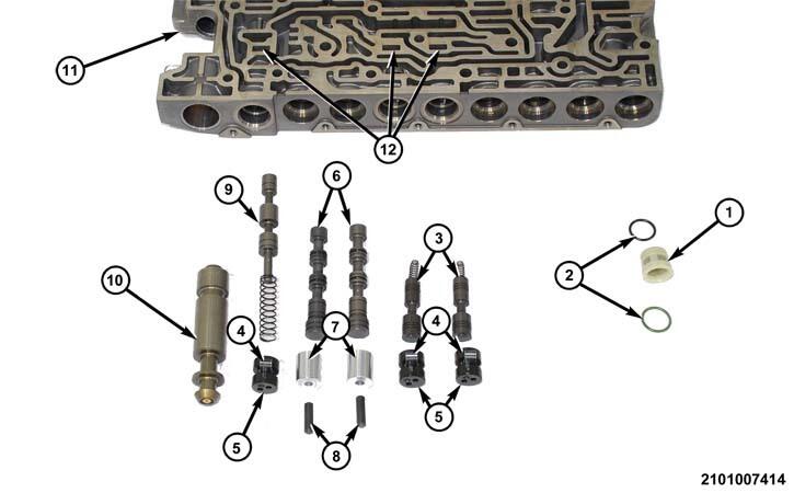
- Rotate the outer valve body (11) to gain access to the pressure and lubrication valves.
- The support plates (3) and spring clip (6) are located in pockets (8) in the outer valve body (1).
- Remove the support plate (3) holding the spring and converter pressure valve (2) in the bore in the outer valve body (1).
- Remove the spring and converter pressure valve (2) from the bore in the outer valve body (1).
- Remove the support plate (3) holding the plug (5), spring and system pressure valve (7) in the bore in the outer valve body (1).
- Remove the plug (5), spring and system pressure valve (7) from the bore in the outer valve body (1).
- Remove the spring clip (6) holding the plug (5), spring and lubrication valve (4) in the bore in the outer valve body (1).
- Remove the plug (5), spring and lubrication valve (4) from the bore in the outer valve body (1).
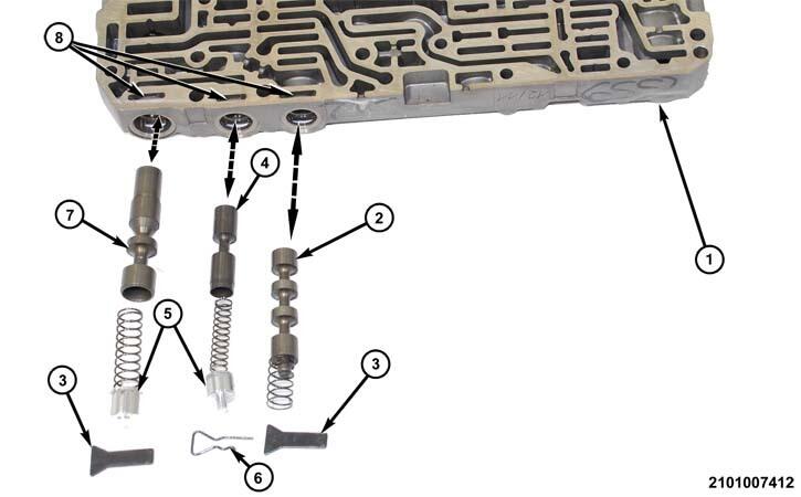
- Place the inner valve body on the clean work surface with the valves bores facing up.NOTE:
The spring clips (2) holding the plugs (1) in the inner valve are located in pockets (2) on the separator plate side of the inner valve body.
- Press each of the valve plugs (1) downward and remove the spring clips (2) holding the valves in the bores in the inner valve body.
- Remove the plug (2), spring and boost valve (1) from the bore in the inner valve body (6).
- Remove the plug (2), spring and solenoid limit valve (4) from the bore in the inner valve body (6).
- Remove the plugs (2), springs and PCV valves (5) from the bores in the inner valve body (6).
- Perform the cleaning and inspection procedures below.